Illumination characteristic selection system for imaging during an ophthalmic laser procedure and associated methods

a technology of illumination characteristic and imaging system, which is applied in the field of system and method for performing laser ophthalmic surgery, can solve the problems of difficult detection of boundary, negative reflection of image processing, and difficulty in locating desired features, and achieve the effect of partial polarization properties

Inactive Publication Date: 2007-06-28
ALCON REFRACTIVEHORIZONS
View PDF1 Cites 9 Cited by
  • Summary
  • Abstract
  • Description
  • Claims
  • Application Information

AI Technical Summary

Benefits of technology

[0005] The present invention is directed to a system and method for optimizing the effects of light sources on viewing and image processing, and for imaging an illuminated object. The system takes advantage of the fact that specularly reflected light (glint) has particular polarization properties compared with diffusely scattered light. The system can comprise means for delivering polarized light to illuminate an object with a polarized beam and means for delivering unpolarized light to illuminate the object with an unpolarized beam. A detector is positioned to receive light from the pol...

Problems solved by technology

Reflections can have a negative impact on image processing, especially if reflections mask an important part of the image.
These sources can be visible in the image of the eye and can cause problems in locating the desired features.
This would cause reflections from the cornea close to the pupil boundary, so that this boundary would be difficult to detect.
The problem is exacerbated if a corneal flap is cut on the eye, as the size of the illumination source reflection grows owing to the roughening of the corneal surface.
However, if the illumination source is far off-axis, accessibility to the patient is reduced, as is the user's working area.
Small pupils, however, can be obscured, which makes them more difficult to track in the presence of distractions.

Method used


Image

  • Illumination characteristic selection system for imaging during an ophthalmic laser procedure and associated methods
  • Illumination characteristic selection system for imaging during an ophthalmic laser procedure and associated methods
  • Illumination characteristic selection system for imaging during an ophthalmic laser procedure and associated methods

Examples


Embodiment Construction

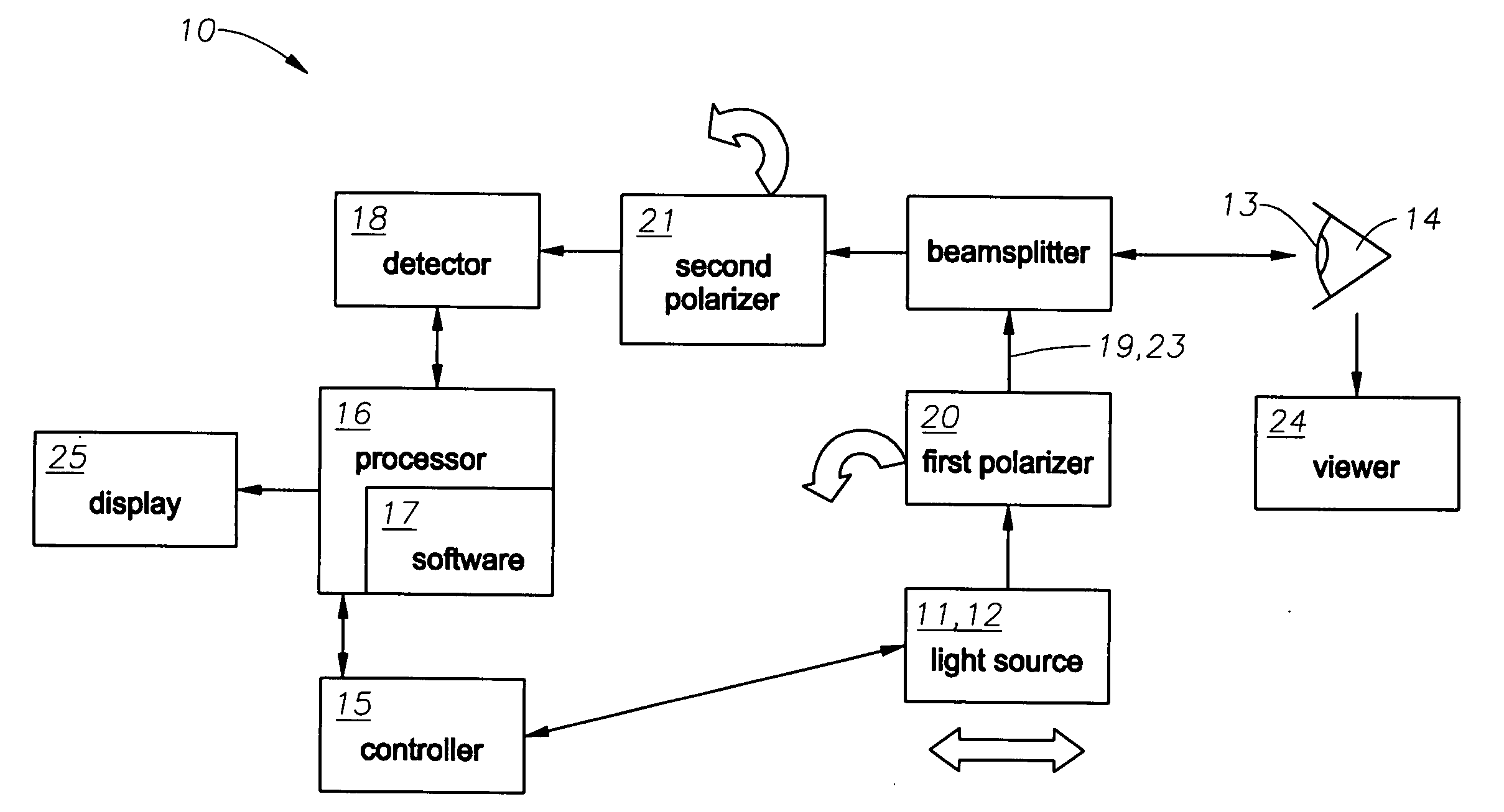
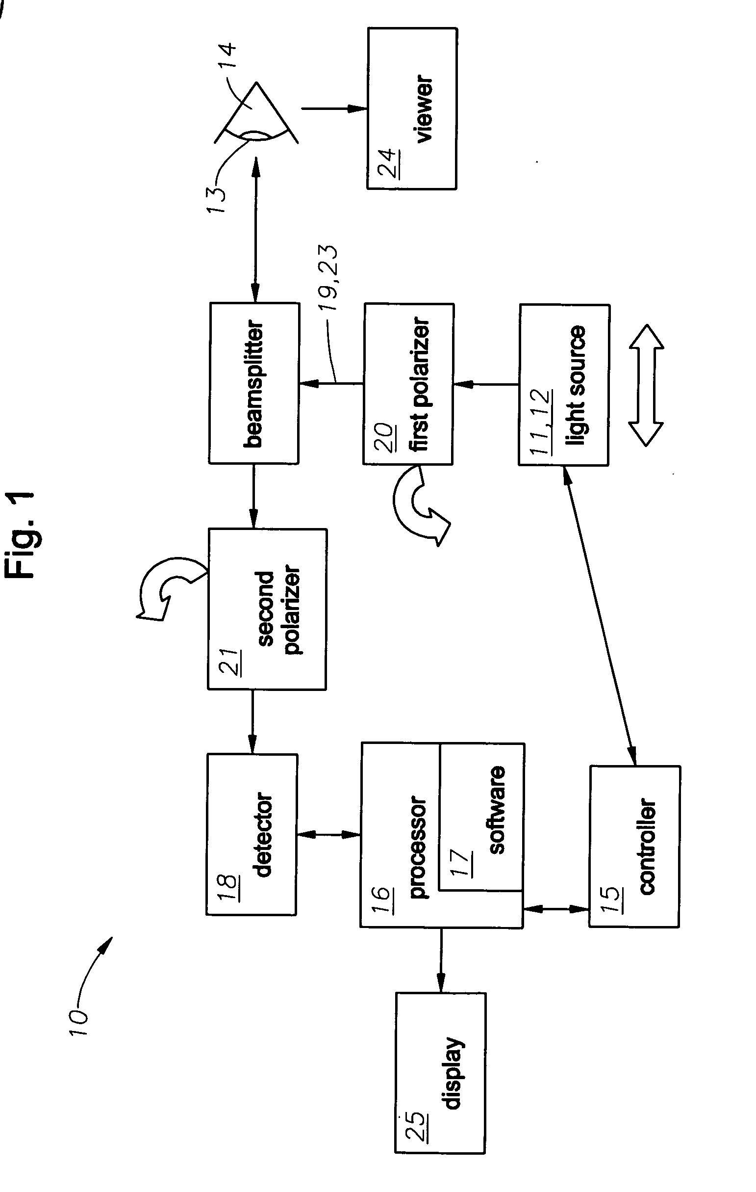
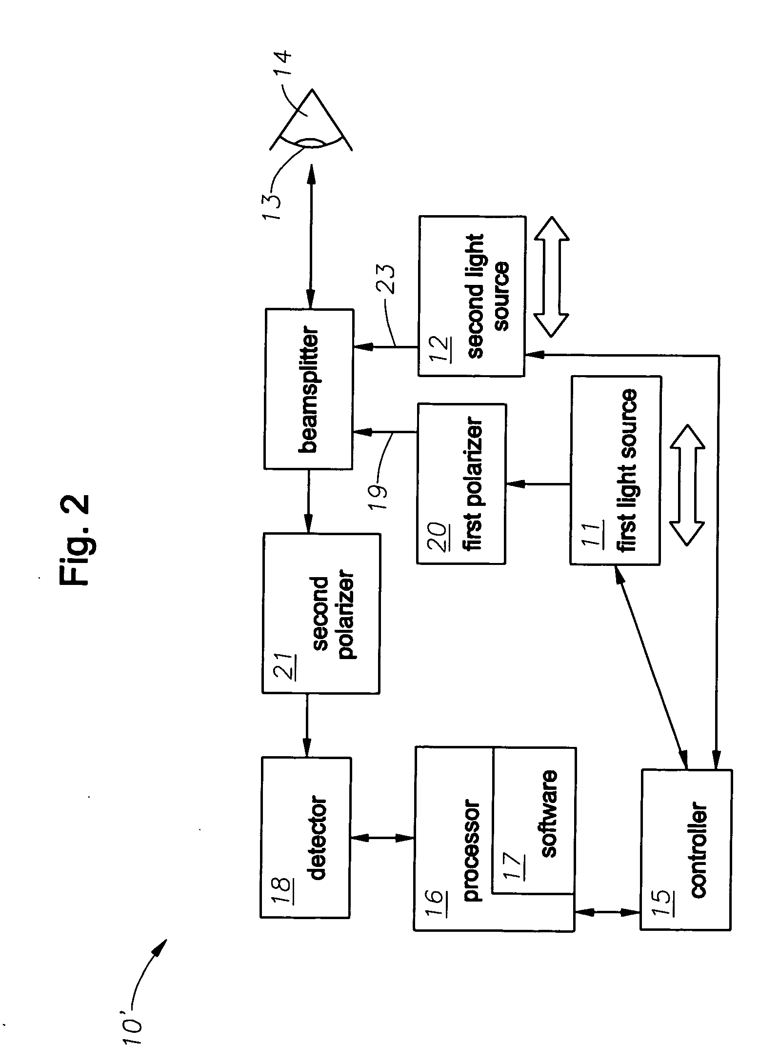
[0009] A detailed description of preferred embodiments of the invention will now be discussed with reference to FIGS. 1 and 2. The system 10 of the present invention can comprise a first and a second light source 11,12 that are positioned to illuminate an object. In the exemplary embodiment, the first 11 and second 12 light source are for illuminating at least a cornea 13 of an eye 14, and, typically, the area around the cornea 13. As shown schematically in FIGS. 1 and 2, the system 10 further includes a controller 15 that is in signal communication with the first 11 and second 12 light source. Signal processing means such as a processor 16 with image processing software 17 resident thereon is in communication with a detector 18, which is positioned to receive light reflected from the eye 14.

[0010] In an embodiment, the first light source 11 is adapted to emit a polarized light beam 19, for which a first polarizer 20 is positioned downstream of the first light source 11, and a seco...


PUM


Abstract

A system for optimizing the effects of light sources on viewing and image processing, and for imaging an illuminated object takes advantage of the fact that specularly reflected light has particular polarization properties compared with diffusely scattered light. The system includes a polarized light source to illuminate an object with a polarized beam and an unpolarized light source for delivering unpolarized light to illuminate the object with an unpolarized beam. A detector is positioned to receive light from the beams reflected from the object. A polarizer is oriented for substantially filtering out specular reflection from the object and for permitting at least a portion of diffuse reflection from the object to pass therethrough. The polarized and unpolarized light sources and the polarizer are controllable for selectively illuminating the object with and detecting light having a selected polarization characteristic as a function of a portion of a procedure being performed.

Description

FIELD OF THE INVENTION [0001] The present invention is directed to a system and method for performing a laser ophthalmic surgical procedure, and, more particularly, to a system and method for adjusting an illumination characteristic during the surgical procedure. BACKGROUND OF THE INVENTION [0002] Reflections can have a negative impact on image processing, especially if reflections mask an important part of the image. For example, in ophthalmic devices it is sometimes necessary to detect and locate features of an eye such as a pupil. One or more illumination sources are typically necessary in order to achieve sufficient image brightness. These sources can be visible in the image of the eye and can cause problems in locating the desired features. For example, a laser refractive surgery system can have an illumination arrangement that places the sources near the optical axis of the camera. This would cause reflections from the cornea close to the pupil boundary, so that this boundary ...

Claims


Application Information

Patent Timeline
IPC IPC(8): A61B3/10
CPCA61B3/156A61F9/008A61F2009/00872A61F9/00A61F9/007
Inventor LEBLANC, RICHARD A.CAMPIN, JOHN A.NGUYEN, PHUOC K.
Owner ALCON REFRACTIVEHORIZONS
Why Eureka
Try Eureka