Broadband antireflection coating

a broadband, anti-reflection technology, applied in the direction of optical elements, lighting and heating apparatuses, instruments, etc., can solve the problems of subtle color change and the like, the anti-reflection coating of related art had quite a few negative effects on the optical characteristics of the optical element, and the optical characteristics of the optical-related device changed, so as to reduce the variations in the transmittance characteristics broaden the bandwidth of the anti-reflection coating

Inactive Publication Date: 2007-06-28
TOYO TSUSHINKI
View PDF10 Cites 8 Cited by
  • Summary
  • Abstract
  • Description
  • Claims
  • Application Information

AI Technical Summary

Benefits of technology

[0013] An advantage of the present invention is to solve the above-described problems, and provides a broadband antireflection coating which further broadens the bandwidth of antireflection coating and reduces variations in transmittance characteristics of the antireflection coating when optical elements are mass-produced.
[0014] The broadband antireflection coating according to the present invention includes: is formed on at least one of an incident surface or an emission surface of an optical element and reduces reflected-light quantity of incident light or emission light, and includes a structure laminated with seven layers of thin films.
[0015] Further, the broadband antireflection coating according to the present invention, on the surface of the optical element, includes the seven layers of laminated films are alternatively laminated with a thin film using a low refractive index material and a thin film using a high refractive index material.
[0016] As mentioned as above, by alternatively laminating seven layers of thin films using the low refractive index material and the high refractive index material, the broadband antireflection coating can broaden the bandwidth of the antireflection coating and reduce variations in the transmittance characteristics of the antireflection coating. When this broadband antireflection coating is formed, for example, on an optical element forming an optical device such as a camera, a subtle change in color can be improved. Further, as the broadband antireflection coating reduces the reduction of transmittance in the ultraviolet band and the infrared band near the visible light band, it is effective in preventing flare and enables to suppress the occurrence of reflection ghost resulting from multiple-reflection from the antireflection coating.
[0017] Furthermore, as the broadband antireflection coating reduces variations in the transmittance characteristics, when an optical element formed with the broadband antireflection coating is used for an optical-related device, the optical characteristics of the optical-related device stabilize, and able to improve a performance of the optical-related device.
[0018] The broadband antireflection coating according to the present invention, on the surface of the optical element, is formed by sequentially laminating a first thin film having MgF2 as a material with a thickness of about 37.7 nm; a second thin film having H4 (a mixture of La and TiO2) as a material with a thickness of about 6.5 nm; a third thin film having MgF2 as a material with a thickness of about 122.5 nm; a fourth thin film having H4 as a material with a thickness of about 13.0 nm; a fifth thin film having MgF2 as a material with a thickness of about 37.7 nm; a sixth thin film having H4 as a material with a thickness of about 130.0 nm; and a seventh thin film having MgF2 as a material with a thickness of about 84.8 nm.

Problems solved by technology

However, the antireflection coating of related art had quite a few negative effects in optical characteristics of the optical element, due to transmittance reduction in an ultraviolet band and an infrared band near the visible light band, when formed to the optical element used in the visible light band.
For example, when the optical element like this was used for an optical device such as a camera, a problem of a subtle change in color and the like had occurred.
Further, the optical element formed with the antireflection coating of related art generates variations in transmitted light quantity in the optical elements when mass-produced, which results in a problem that the optical characteristics of the optical-related devices change depending on an individual optical element.

Method used


Image

  • Broadband antireflection coating
  • Broadband antireflection coating
  • Broadband antireflection coating

Examples


first embodiment

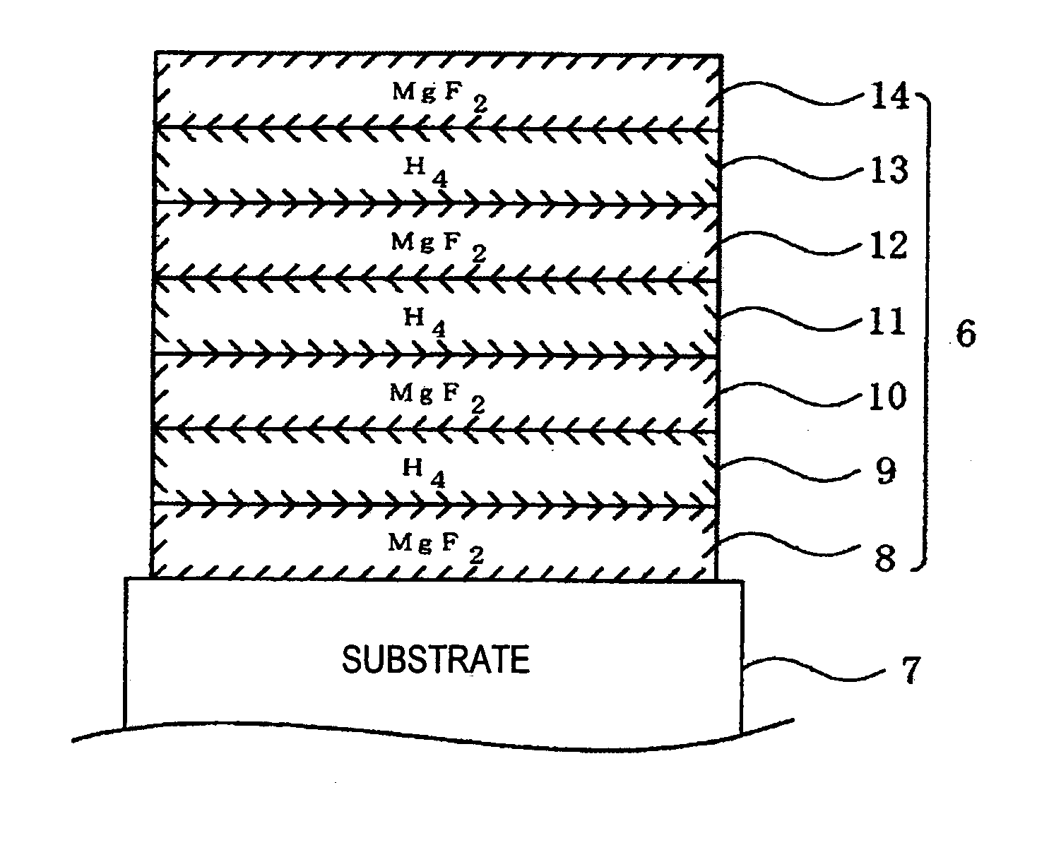
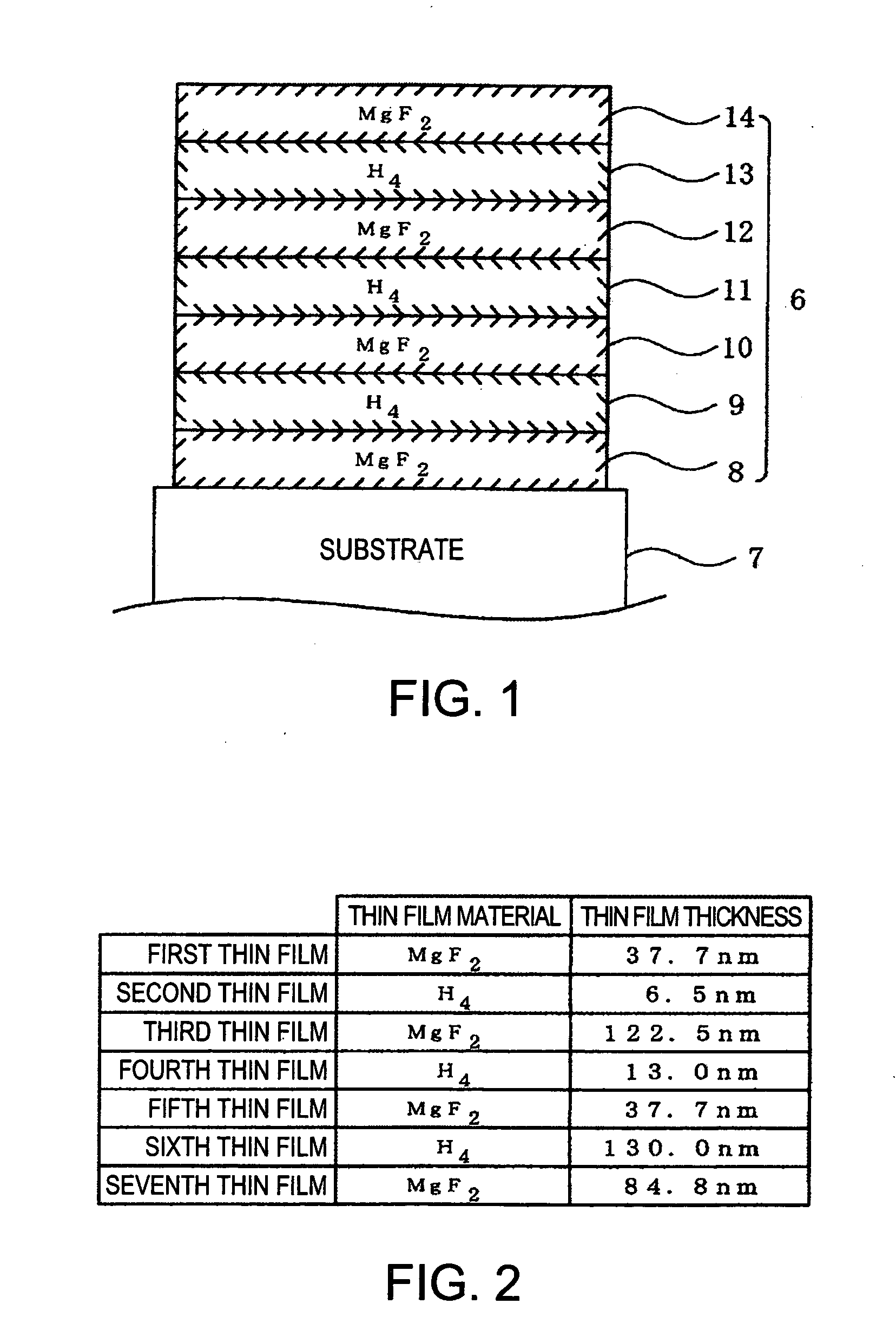
[0033] In the first embodiment, H4 ( a mixture of La and TiO2) which has a refractive index of approximately 2.00 is used as the high refractive index material for thin film, and MgF2 which has a refractive index of approximately 1.38 is used as the low refractive index material for thin film. With that, a material for the second thin film 9 is to be H4, a material for the third thin film 10 is to be MgF2, a material for the fourth thin film 11 is to be H4, a material for the fifth thin film 12 is to be MgF2, a material for the sixth thin film 13 is to be H4, and a material for the seventh thin film 14 is to be Mg F2.

[0034] Next, a calculation formula to obtain respective optimum thicknesses of seven thin film layers forming the broadband antireflection coating 6 is to be shown and the concrete values of the thickness is to be described.

[0035] When a physical film thickness of each layer is represented as dm (m=1, 2, 3, 4, 5, 6, and 7, indicating the position of layer of the thin f...

second embodiment

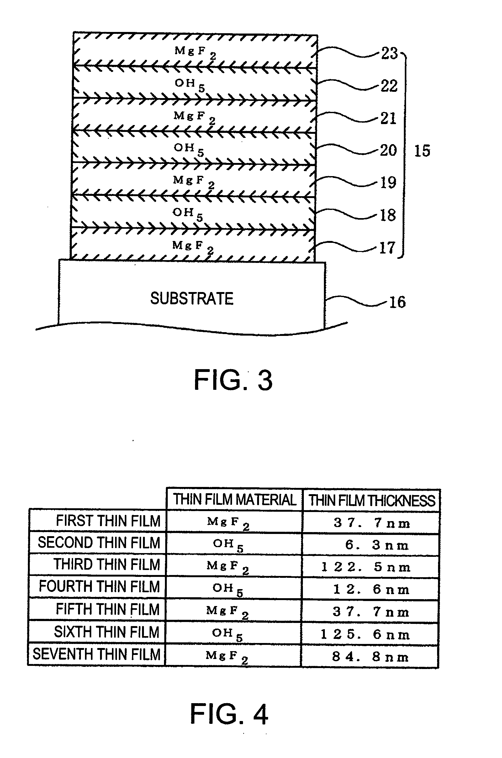
[0050] In the second embodiment, OH5 which has a refractive index of approximately 2.07 is used as the high refractive index material for thin film, and MgF2 which has a refractive index of approximately 1.38 is used as the low refractive index material for thin film. With that, a material for the second thin film 18 is to be OH5, a material for the third thin film 19 is to be MgF2, a material for the fourth thin film 20 is to be OH5, a material for the fifth thin film 21 is to be MgF2, a material for the sixth thin film 22 is to be OH5, and a material for the seventh thin film 23 is to be MgF2.

[0051] Next, a calculation formula to obtain respective thicknesses of seven thin film layers forming the broadband antireflection coating 15 is to be shown and the concrete values of the thickness is to be described.

[0052] As in a case of the first embodiment, when a physical film thickness of each layer is represented as dm (m=1, 2, 3, 4, 5, 6, and 7, indicating the position of layer of th...


PUM

PropertyMeasurementUnit
thicknessaaaaaaaaaa
thicknessaaaaaaaaaa
thicknessaaaaaaaaaa

Abstract

A broadband antireflection coating formed on at least one of an incident surface or an emission surface of an optical element and reduces reflected-light quantity of incident light or emission light, includes: a structure laminating seven layers of a thin film.

Description

BACKGROUND OF THE INVENTION [0001] 1. Technical Field [0002] The present invention relates to a broadband antireflection coating. More particularly, the present invention relates to a broadband antireflection coating which is formed on incident and emission surfaces of an optical element, and broadens the bandwidth of transmittance characteristics and reduces variations in the transmittance characteristics of an antireflection coating which reduces reflected-light quantity of incident light. [0003] 2.Related Art [0004] An antireflection coating which reduces reflection of light at incident and emission surfaces is formed on incident and emission surfaces of an optical element forming optical-related devices such as lens, prisms and wavelength plates, to prevent attenuation of light quantity of incident light. JP-A-2000-199802, JP-A-2001-235602 and JP-A-2002-311209 are examples of the related arts. [0005]FIG. 7 is a diagram showing a configuration example of an antireflection coating...

Claims


Application Information

Patent Timeline
Patent Type & Authority Applications(United States)
IPC IPC(8): F21V9/04
CPCG02B1/115C03C17/34B32B7/02
Inventor YAMAGUCHI, KOJI
Owner TOYO TSUSHINKI
Why Eureka
Try Eureka