Plasma television and power supply control device

a technology of power supply control and plasma television, which is applied in the direction of emergency protective arrangements for limiting excess voltage/current, television systems, instruments, etc., can solve the problems of not paying attention to the different malfunction severity of various portions of the apparatus, so as to prevent the apparatus from breaking down and avoid unnecessary shutting off of the power supply

Inactive Publication Date: 2007-06-28
ROHM & HAAS ELECTRONICS MATERIALS CMP HLDG INC +1
View PDF3 Cites 13 Cited by
  • Summary
  • Abstract
  • Description
  • Claims
  • Application Information

AI Technical Summary

Benefits of technology

[0013] The present invention discloses the combination of a plasma television set and a power supply control device that can realize one function to prevent an apparatus from breaking down and another function to avoid unnecessary shutting off of a power supply with an appropriate balance of the both functions.
[0018] Therefore, as to the output voltages whose abnormal values may cause serious damages, the judgment that the main power supply should be left OFF can be made at the early time. In consequence, serious failures due to malfunctions of the portions targeted for examination can be prevented from occurring. On the other hand, as to the output voltages whose abnormal values may not cause serious damages at once, the judgment whether the abnormal values are due to a real malfunction or due to temporal inflow of noises can be accurately made through a plurality of abnormal value detections, resulting in the right judgment whether the main power supply should be left OFF or not.
[0022] The output voltages from the standby voltage generation unit and the specified output voltage other than the above-mentioned sustaining voltage from the sustaining voltage generation unit have the low potential to cause damage to the plasma display even if their values are abnormal. Therefore the numbers of the abnormal values detections related to these voltages are set larger and the judgment whether the abnormal values are due to malfunctions or due to temporal noises can be cautiously decided. In consequence, the false operation, where the main power supply is shut off even if there is no need to stop the main power supply because the abnormal values are due to temporal noises, can be prevented.
[0029] As explained above, the present invention can provides one function to prevent the apparatus from breaking down due to malfunctions and another function to avoid unnecessary shutting off of the power supply with an appropriate balance of the both functions because the following measures are adopted:

Problems solved by technology

Here, among circuits that constitute an apparatus, the malfunctions of some circuits are liable to cause the failure of the above-mentioned display panel and the like, and the malfunctions of other circuits may not directly cause the failure of the above-mentioned display panel and the like, that is, there are various circuits with different malfunction severities mixed in the apparatus.
In above-mentioned prior arts, however, attention is not paid to the different malfunction severities of various portions that constitute an apparatus.
Therefore, there is an inappropriate case where the hasty decision that a power supply should be shut off is made even though there is enough time to judge whether the detection of abnormal voltage values have been due to a real malfunction or due to simple inflow of noises or there is another inappropriate case where, as contrasted with the former case, the above-mentioned detection process is repeated many times although the situation is so urgent that the power supply should be shut off at once with the adverse effect due to a real malfunction taken into account.

Method used


Image

  • Plasma television and power supply control device
  • Plasma television and power supply control device
  • Plasma television and power supply control device

Examples


Embodiment Construction

[0040] The detailed description set forth below in connection with the appended drawings is intended as a description of presently preferred embodiments of the invention and is not intended to represent the only forms in which the present invention may be constructed and or utilized.

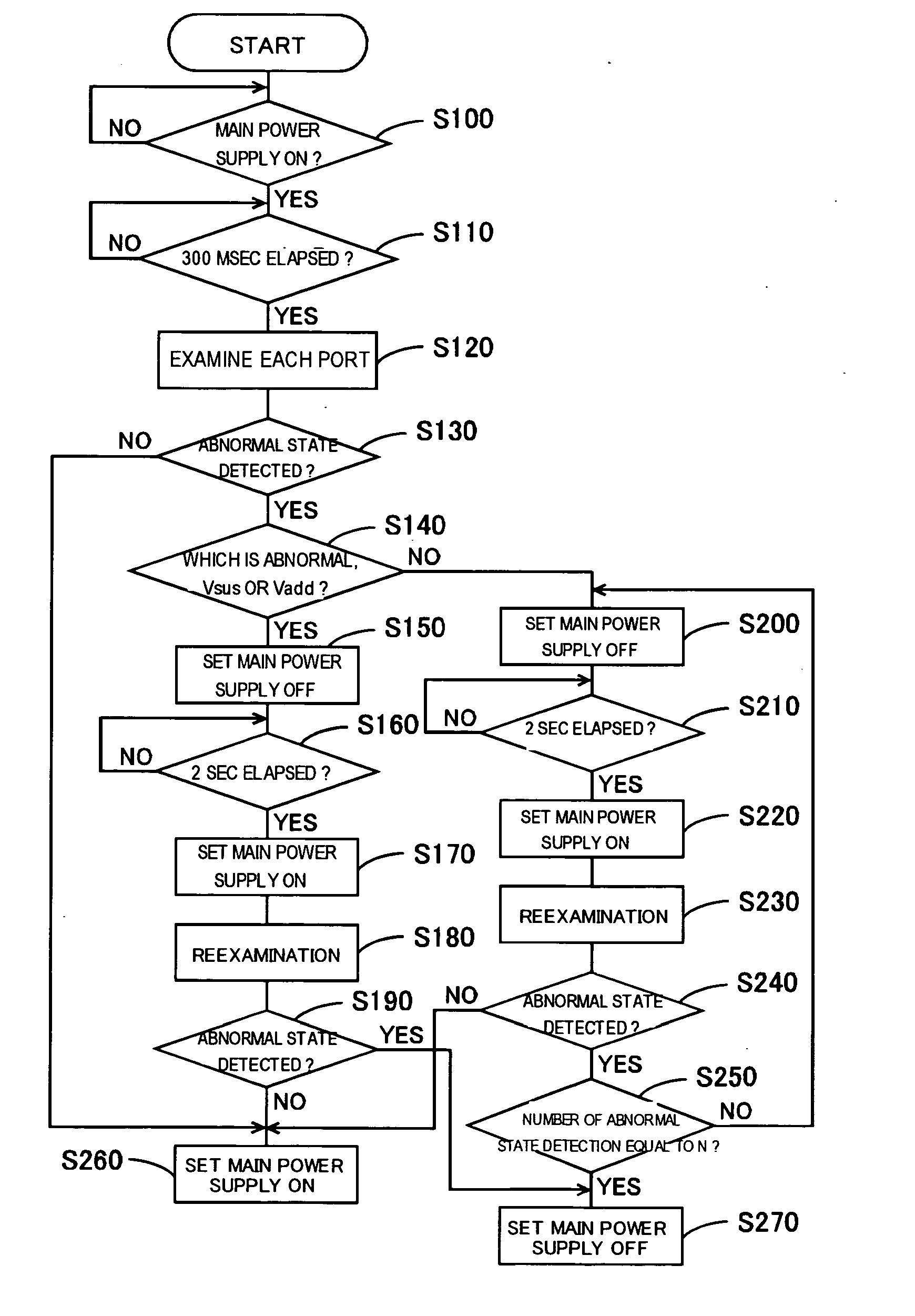
[0041] An embodiment of the present invention will be described in the following sequence: [0042] (1) Configuration of a plasma television [0043] (2) Configuration of a power supply circuit and others [0044] (3) Concrete contents of a power supply control processing [0045] (4) Conclusion

[0046] (1) Configuration of Plasma Television Set

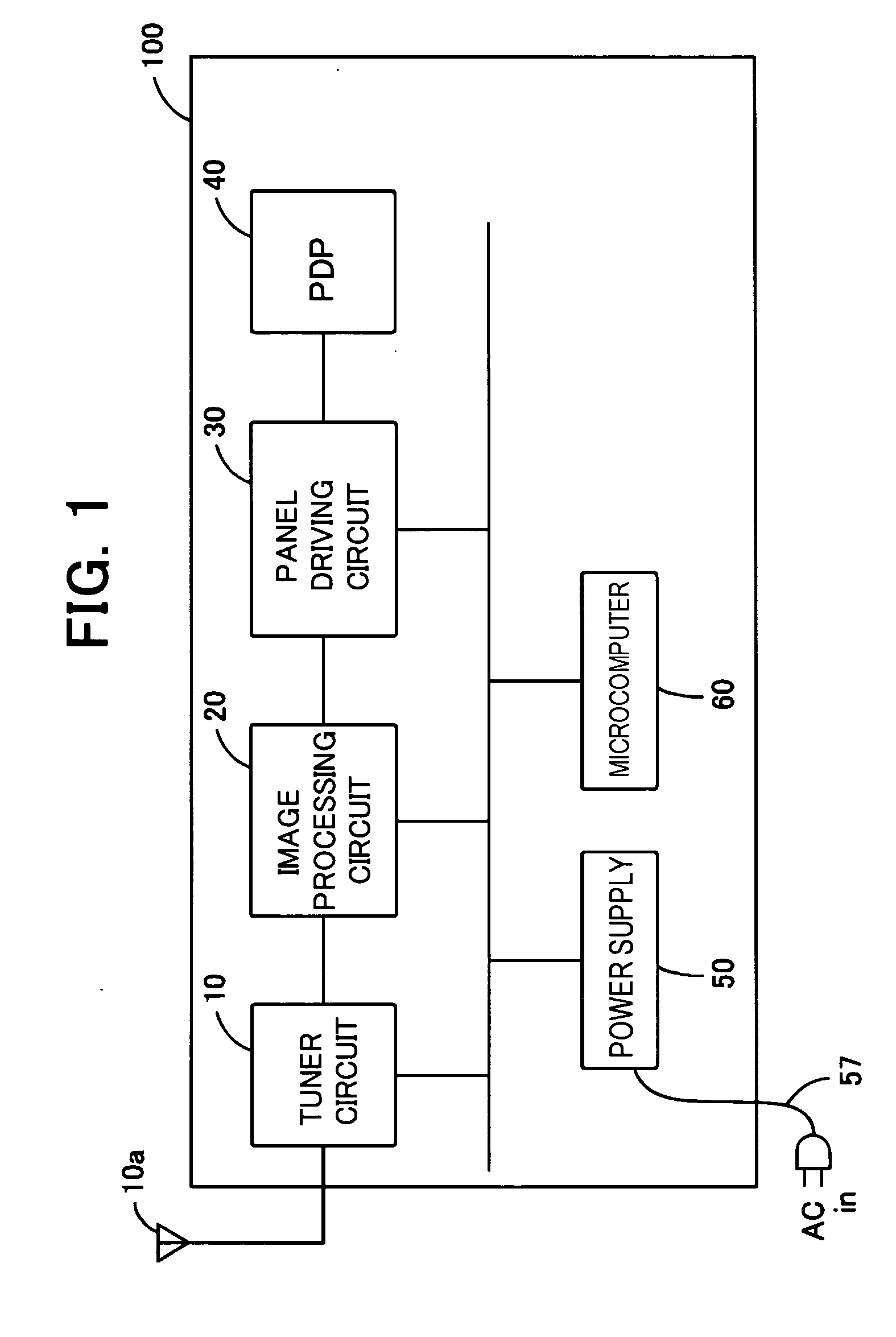
[0047]FIG. 1 is a block diagram showing a schematic configuration of a plasma television set related to the present invention.

[0048] As shown in FIG. 1, the plasma television set 100 is mainly composed of a plasma display panel (PDP for short hereafter) 40, an image processing circuit 20, a tuner circuit 10, a microcomputer 60, a panel driving circuit 30, and a power su...


PUM


Abstract

A microcomputer 60 takes in voltages output from the sustaining voltage Vsus generation circuit 52, the addressing voltage Vadd generation circuit 53, and the standby voltage generating circuit 54 via A / D input ports 1 through 6 mounted on the microcomputer board, and performs examinations to judge whether abnormal values are detected about the voltages. If there is at least one abnormal value detected, the main power supply is set OFF and after a predetermined time the main power supply is set ON again to perform a reexamination. If the number of times when abnormal values about a certain voltage are detected reaches the number of abnormal value detections N, the main power supply is left OFF. The number of abnormal value detections N for the Vsamp, the Vset, the Ve or the Vscan, is set larger than the number of abnormal value detections set for the Vsus or the Vadd.

Description

CROSS-REFERENCES TO RELATED APPLICATIONS [0001] The present application is related to the Japanese Patent Application No. 2005-372259, filed Dec. 26, 2005, the entire disclosure of which is expressly incorporated by reference herein. BACKGROUND OF THE INVENTION [0002] (1) Field of the Invention [0003] The present invention relates to a plasma television and a power supply control device. [0004] (2) Description of the Related Art [0005] As one conventional art to protect a television receiver, the protection method of a television receiver to prohibit the main power supply of a microcomputer from being set ON after the number of protection operations to set the main power supply OFF reaches the predetermined number is well known (Refer to Japanese Patent Laid-Open No. H4-79583). [0006] In addition, a television receiver with a function that disables the stop function for setting the switching circuit OFF when noises are detected in the main body of the television receiver for a prede...

Claims


Application Information

Patent Timeline
Patent Type & Authority Applications(United States)
IPC IPC(8): H02H3/20G09G3/20G09G3/296H04N5/63
CPCH04N5/63H04N17/04
Inventor NISHIMURA, SHOICHIRO
Owner ROHM & HAAS ELECTRONICS MATERIALS CMP HLDG INC
Why Eureka
Try Eureka