Fan system

a fan system and fan body technology, applied in the direction of positive displacement liquid engine, electric generator control, piston pump, etc., can solve the problems of affecting the heat dissipation of the electronic system, and achieve the effect of reducing power consumption and keeping heat dissipation

Active Publication Date: 2007-06-28
DELTA ELECTRONICS INC
View PDF13 Cites 4 Cited by
  • Summary
  • Abstract
  • Description
  • Claims
  • Application Information

AI Technical Summary

Benefits of technology

[0011] As mentioned above, a fan system according to the present invention utilizes a first fan driving at least one second fan to rotate, an electric energy generated by the second fan is recycled and stored in an energy storage. The energy storage keeps supplying power when the driving source is out of order or the fan is rotating in lower rotation speed. That is, the energy storage can be used as an emergency driving source to keep heat dissipation when the driving source is out of order or the fan is rotating at lower rotation speed. Compared with the prior art, the present invention can store energy by itself for re-usage so that the energy is thus completely used. The effects of power saving, reducing power consumption and green product are achieved.

Problems solved by technology

The heat dissipation of the electronic system will be affected if the voltage source P is out of order.

Method used


Image

  • Fan system
  • Fan system
  • Fan system

Examples


first embodiment

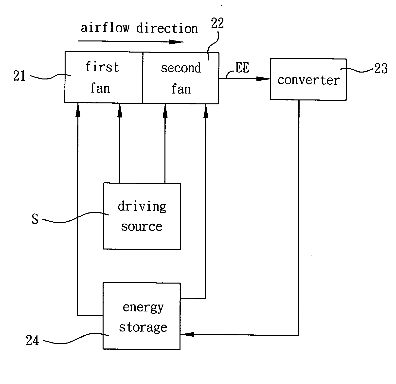
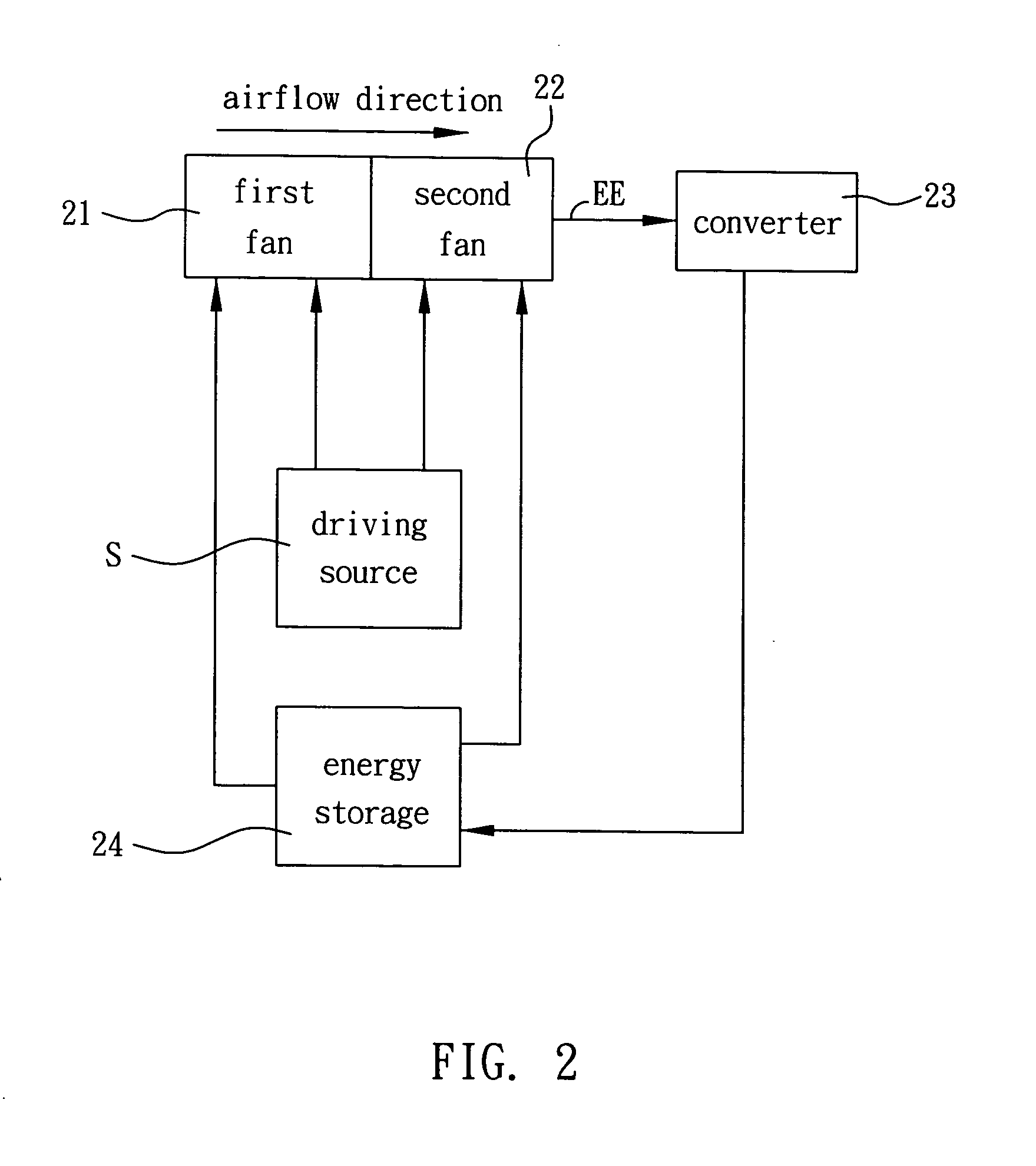
[0019] As shown in FIG. 2, a fan system 2 according to the present invention includes a first fan 21, a second fan 22 and an energy storage 24. The fan system 2 is electrically connected with a driving source S. The first fan 21 and the second fan 22 are disposed in series (according to the airflow direction). The driving source S is electrically connected with the first fan 21 and the second fan 22. The energy storage 24 is electrically connected with the second fan 22. In addition, the energy storage 24 can be further connected with the first fan 21. In this embodiment, the driving source S can be a generator or a power supply. The first fan 21 and / or the second fan 22 can be an axial fan. The energy storage 24 can be a battery or a chargeable battery.

[0020] The fan system 2 is operated as described below. The second fan 22 is rotated by the first fan 21 when the first fan 21 is driven to rotate by the driving source S. The coils of motor of the second fan 22 induce an electric en...

second embodiment

[0023] As shown in FIG. 3, a fan system 3 according to the present invention is electrically connected with a driving source S. The fan system 3 includes a fan 31 and an energy storage 33. The fan 31 has a first impeller 311 and a second impeller 312. The first impeller311 and the second impeller 312 are coupled in series and are accommodated in a frame (not shown). The driving source S is electrically connected with the first impeller 311 and the second impeller 312.

[0024] The fan system 3 further includes a converter 32 electrically connected with the second impeller 312 and the energy storage 33. The energy storage 33 is electrically connected with the second impeller 312, and can be further connected with the first impeller 311. In this embodiment, the driving source S can be a generator or a power supply. The fan 31 can be an axial fan. The energy storage 33 is preferably a battery or a chargeable battery.

[0025] The fan system 3 is operated as described below. The second impel...

third embodiment

[0027] As shown in FIG. 4, a fan system 4 according to the present invention is electrically connected with a driving source S. The fan system 4 includes a first fan 41, a plurality of second fans 42 and an energy storage 44. The fan system 4 further includes a plurality of converters 43. The converters 43 can be replaced with a single converter electrically connected with the second fans 42. The driving source S is electrically connected with the first fan 41 and the second fan 42.

[0028] In this embodiment, the constructions and functions of the first fan 41, the second fans 42, the converters 43 and the energy storage 44 are the same as those described in the first embodiment, so the detailed descriptions thereof is omitted. In addition, the first or second fan can be a high-pressure fan or an axial-flow fan.

[0029] The difference between this embodiment and the first embodiment is that the first fan 41 is respectively connected with the second fans 42 in series, and the second fa...


PUM


Abstract

A fan system is electrically connected with a driving source and includes a first fan, a second fan and an energy storage. The second fan is rotated by the first fan for generating an electric energy. The energy storage is electrically connected with the second fan for storing the electric energy and keep supplying power when the driving source is out of order or the fan is rotating in lower rotation speed.

Description

BACKGROUND OF THE INVENTION [0001] 1. Field of Invention [0002] The present invention relates to a fan system, and more particularly to a fan system capable of storing energy by itself for re-usage. [0003] 2. Related Art [0004] Accompanying to the development of technology, the functionality of electronic system is upgraded and the integration of electronic devices is also raised. Electronic system is generally disposed at least one fan for heat dissipation to keep electronic system being normally operated. [0005] In order to enhance the effect of heat dissipation, a plurality of fans are connected with each other in series to raise the pressure and volume of airflow. As shown in FIG. 1, a conventional fan system 1 includes a first fan 11 and a second fan 12. An external voltage source P is connected with the first fan 11 and the second fan 12 when the first fan 11 and the second fan 12 are connected in series. However, the second fan 12 is rotated by the first fan 11 and needs not ...

Claims


Application Information

Patent Timeline
Patent Type & Authority Applications(United States)
IPC IPC(8): F01D15/12
CPCF04D25/166H05K7/20209
Inventor WU, HENG-YUCHIU, CHUN-LUNGTSAI, MING-SHI
Owner DELTA ELECTRONICS INC
Why Eureka
Try Eureka