Propeller shaft

a technology of shaft and shaft shaft, applied in the direction of shaft and bearing, clutch, rotary machine parts, etc., can solve the problems of difficult to achieve the desired friction characteristics of resin coating, difficult to make the coefficient of static friction and coefficient of dynamic friction substantially equal, and achieve the effect of suppressing wear

Inactive Publication Date: 2007-06-28
TOYOTA JIDOSHA KK
View PDF2 Cites 17 Cited by
  • Summary
  • Abstract
  • Description
  • Claims
  • Application Information

AI Technical Summary

Benefits of technology

[0006] The present invention was made to solve the above-described problems. An object of the present invention is to provide a propeller shaft capable of making a coefficient of static friction and a coefficient of dynamic friction substantially equal to each other and suppressing wear.

Problems solved by technology

As the spline portion is strongly affected by a surface of a counterpart sliding member, it is difficult to obtain desired friction characteristics with the resin coating.
Namely, it is difficult to make a coefficient of static friction and a coefficient of dynamic friction substantially equal to each other.
Patent Document 2 discloses a technique to apply a plastic coating to a spline portion, however, desired friction characteristics cannot be obtained either.

Method used


Image

  • Propeller shaft
  • Propeller shaft
  • Propeller shaft

Examples


Embodiment Construction

[0022] An embodiment of the present invention will be described hereinafter with reference to the drawings. In the embodiment below, as the same or corresponding elements have the same reference characters allotted, detailed description thereof will not be repeated.

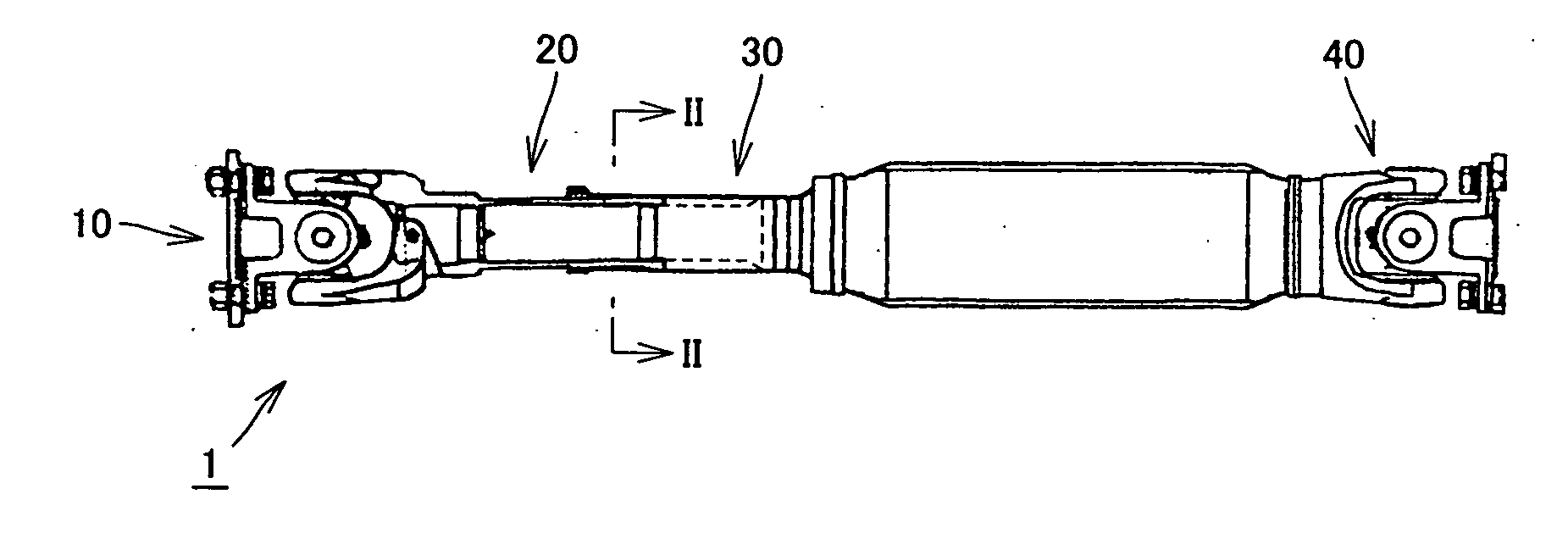
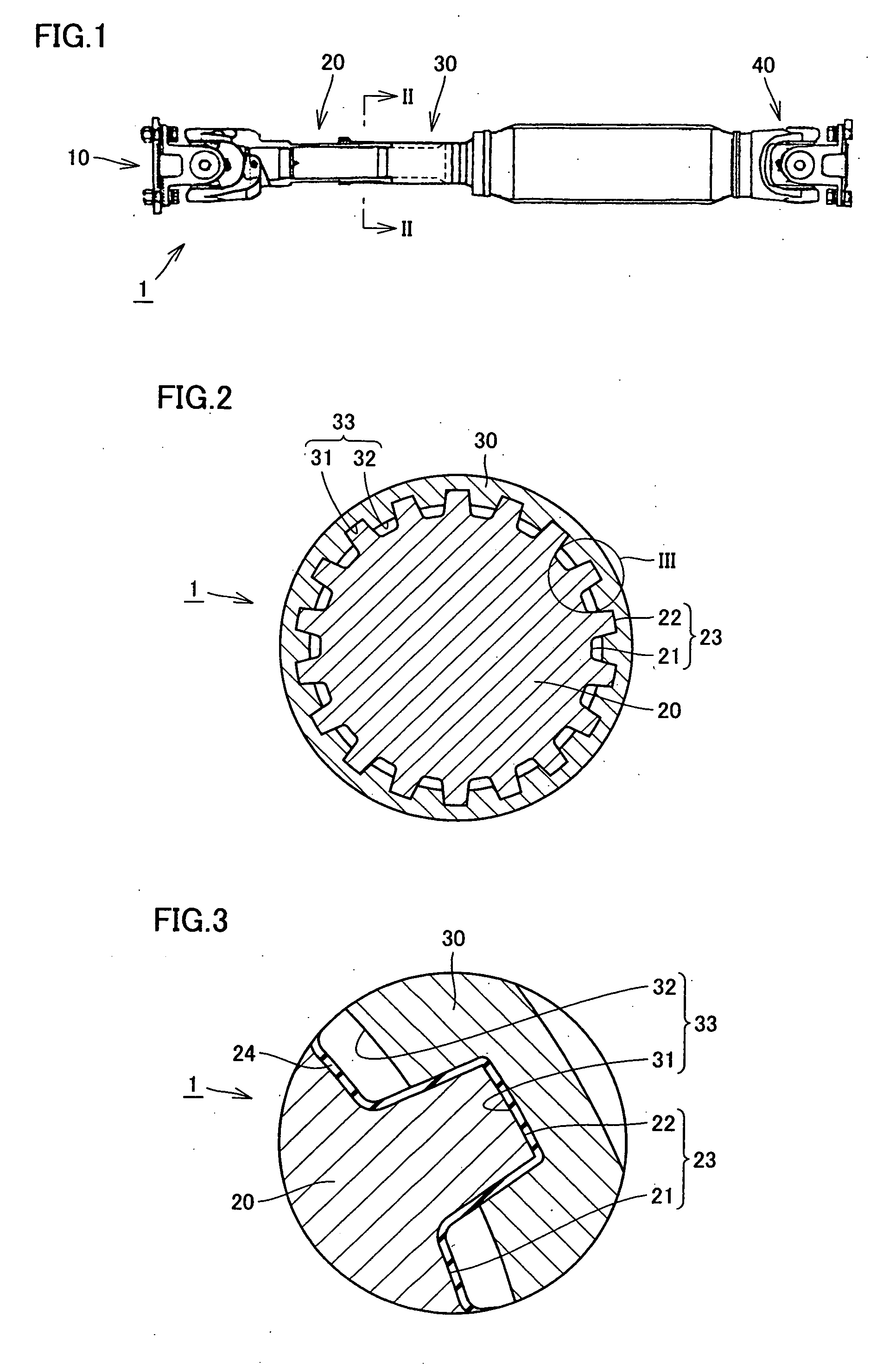
[0023]FIG. 1 is a cross-sectional view of a propeller shaft according to a first embodiment of the present invention. FIG. 2 is a cross-sectional view along the line II-II in FIG. 1. Referring to FIGS. 1 and 2, a propeller shaft 1 according to the first embodiment of the present invention has universal joints 10, 40 provided on left and right ends respectively, a spline shaft 20 connected to universal joint 10, and a spline sleeve 30 meshing with spline shaft 20. Spline sleeve 30 moves in a longitudinal direction with respect to spline shaft 20, so that the total length of propeller shaft 1 extends or contracts. As shown in FIG. 2, spline sleeve 30 has a hollow cylindrical shape, and splines 33 formed by a recessed porti...


PUM


Abstract

A propeller shaft having high wear resistance is provided. The propeller shaft has a spline shaft and a spline sleeve meshing with each other, and a DLC coating is applied to any one of the spline shaft and the spline sleeve. The DLC coating has surface roughness Ra of 0.5 μm or smaller.

Description

[0001] This nonprovisional application is based on Japanese Patent Application No. 2005-379125 filed with the Japan Patent Office on Dec. 28, 2005, the entire contents of which are hereby incorporated by reference. FIELD OF THE INVENTION [0002] The present invention relates to a propeller shaft, and more particularly to a propeller shaft in which a spline shaft portion and a spline sleeve portion mesh with each other and perform frictional sliding with respect to each other. DESCRIPTION OF THE BACKGROUND ART [0003] Conventionally, for example, Japanese Patent Laying-Open Nos. 09-105419 (Patent Document 1) and 08-109918 (Patent Document 2) disclose a propeller shaft. [0004] Patent Document 1 discloses a technique to apply a resin coating to a spline portion. As the spline portion is strongly affected by a surface of a counterpart sliding member, it is difficult to obtain desired friction characteristics with the resin coating. Namely, it is difficult to make a coefficient of static f...

Claims


Application Information

Patent Timeline
Patent Type & Authority Applications(United States)
IPC IPC(8): F16C3/00
CPCF16C3/03F16D3/06F16D2300/10F16C2240/54
Inventor AZUMA, HITOSHITAKEUCHI, SHINICHITASHIRO, HIROAKIYAMAMOTO, TAKEOOZAKI, YOSHINORIFUWA, YOSHIOOGAWA, MASAAKI
Owner TOYOTA JIDOSHA KK
Why Eureka
Try Eureka