Periodic rate sensor self test

a self-testing, sensor technology, applied in the field of motion sensors, can solve the problems of not being able to detect problems in a timely fashion, increasing the operation time of motion sensors between self-tests,

Inactive Publication Date: 2007-06-28
DOLL KENNETH +1
View PDF4 Cites 39 Cited by
  • Summary
  • Abstract
  • Description
  • Claims
  • Application Information

AI Technical Summary

Problems solved by technology

Typically, the self test is carried out during initial vehicle start-up and will generate an error code if the signal conditioning circuit determines that the senor output signal exceeds a predetermined threshold Additionally, upon detecting a malfunctioning sensor, the self test capability may disable the sensor output so an erroneous signal is not sent to the ECU.
However, because vehicles are operated for increasingly lengthy periods of time, the operational time of motion sensors between self tests also has increased.
As a result, if motion sensors begin to malfunction the problem may not be detected in a timely fashion.

Method used


Image

  • Periodic rate sensor self test
  • Periodic rate sensor self test
  • Periodic rate sensor self test

Examples


Embodiment Construction

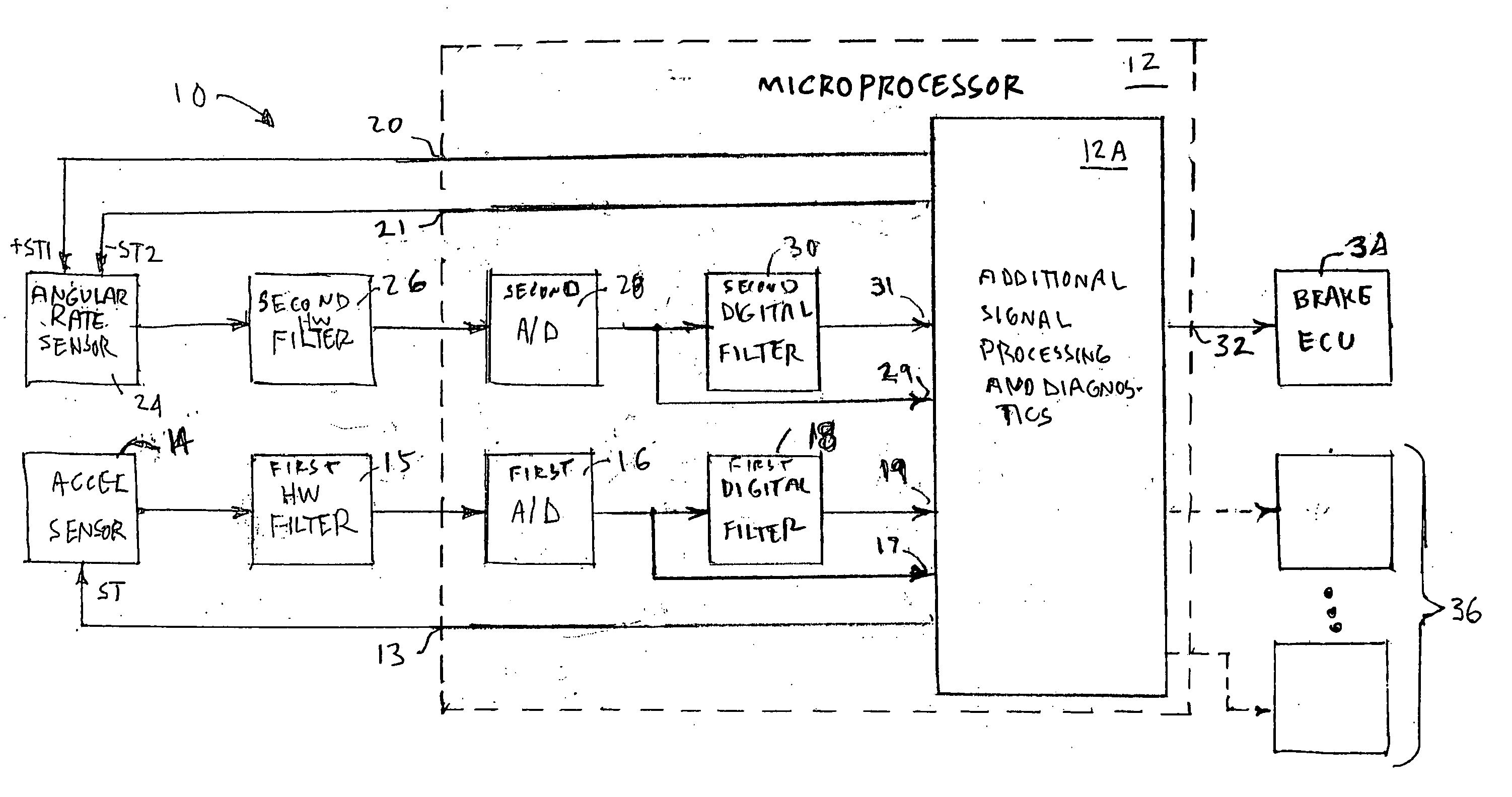
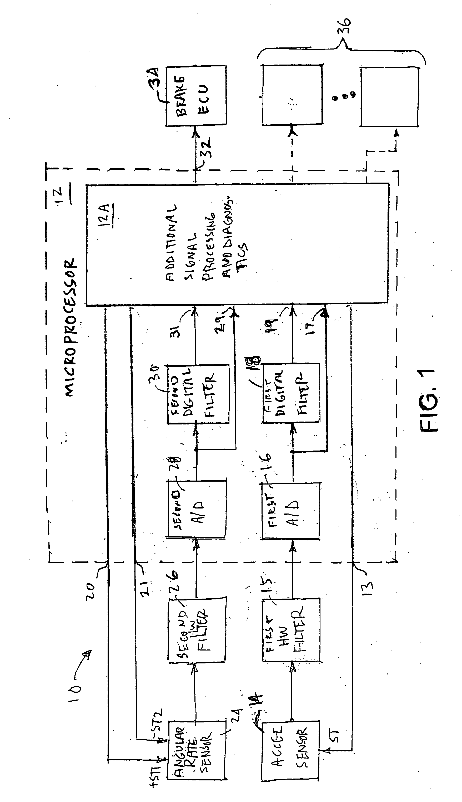
[0027] Referring now to the drawings, there is illustrated in FIG. 1 a portion of a control circuit 10 for an electronic vehicular brake control system (not shown) in accordance with the invention. The control circuit 10 includes a microprocessor 12 having an acceleration sensor test signal output port 13 that is connected to a test signal input port of an acceleration sensor 14. The acceleration sensor 14 has output port connected through a first analog hardware anti-aliasing filter 15 to the input of a first analog to digital converter 16. As shown in FIG. 1, the first analog to digital converter 16 is included in the microprocessor 12. The output of the first analog to digital converter 16 is connected to both an acceleration sensor test signal input port 17 of a signal processing and diagnostic portion 12A of the microprocessor 12 and the input of a first digital filter 18. As shown in FIG. 1, the first digital filter 18 is included in the microprocessor 12. The first digital fi...


PUM


Abstract

A periodic test signal is injected into a motion sensor and the sensor output is compared to a threshold to determine whether the sensor is functioning properly.

Description

CROSS-REFERENCE TO RELATED APPLICATIONS [0001] Not Applicable BACKGROUND OF THE INVENTION [0002] This invention relates in general to motion sensors and in particular to a method for periodically testing the operation of such sensors. [0003] Vehicle electronically controlled brake systems are becoming increasing sophisticated to include the capability to correct vehicle directional movement upon detection of an undesired vehicle motion, such as, for example, loss of directional control on a low mu surface or potential vehicle roll over. Such detection typically involves motion sensors, to include accelerometers and / or angular rate sensors and also usually includes input from other vehicle operating parameter sensors, such as, for example, wheel speed sensors and a steering angle sensor. Vehicle brake control systems typically include an Electronic Control Unit (ECU) that receives the various sensor output signals. A microprocessor within the ECU that is controlled by a stored algori...

Claims


Application Information

Patent Timeline
Patent Type & Authority Applications(United States)
IPC IPC(8): G06F19/00
CPCB60T8/885B60T2270/406B60T2270/413G01M17/00G06F7/00G06F11/22
Inventor DOLL, KENNETHSPIEKER, ARNOLD
Owner DOLL KENNETH
Why Eureka
Try Eureka