Window lift mechanism

Inactive Publication Date: 2007-07-05
FENELON PAUL J
View PDF86 Cites 15 Cited by
  • Summary
  • Abstract
  • Description
  • Claims
  • Application Information

AI Technical Summary

Benefits of technology

[0008] Historically, the overmolded worm gear shaft manufactured from approximately 0.5 inches diameter steel is utilized to provide sufficient rigidity to maintain worm-to-worm gear interaction (i.e., center-to-center distance) while occupying minimum space. In current worm gear motor transmissions, space is required so that an efficient shock absorber drive coupler mechanism can be incorporated into the space and ensure a useful worm gear life.
[0009] According to the present disclosure, the improved efficiency of rack and pinion regulator systems has been discovered to allow for the total elimination and/or reduction of the worm gear shock absorber drive coupler mechanism for closures requiring stall torques less than 8 N-m and stall torques between 8 to 10 N-m, respectively. The elimination/reduction of the shock a

Problems solved by technology

The scissor-type and drum and cable mechanisms are typically mechanically inefficient, prohibiting the use of light-weight materials and requiring the use of relatively large motors to drive the system.
The large motors necessarily require increased space and electrical power and also increase the weight of the system.
This results in excessive worm gear speed in the range of 3000 to 4000 RPM which causes excessive worm gear tooth shock and armature n

Method used


Image

  • Window lift mechanism
  • Window lift mechanism
  • Window lift mechanism

Examples


Example

[0016] The following description of the preferred embodiment(s) is merely exemplary in nature and is in no way intended to limit the invention, its application, or uses.

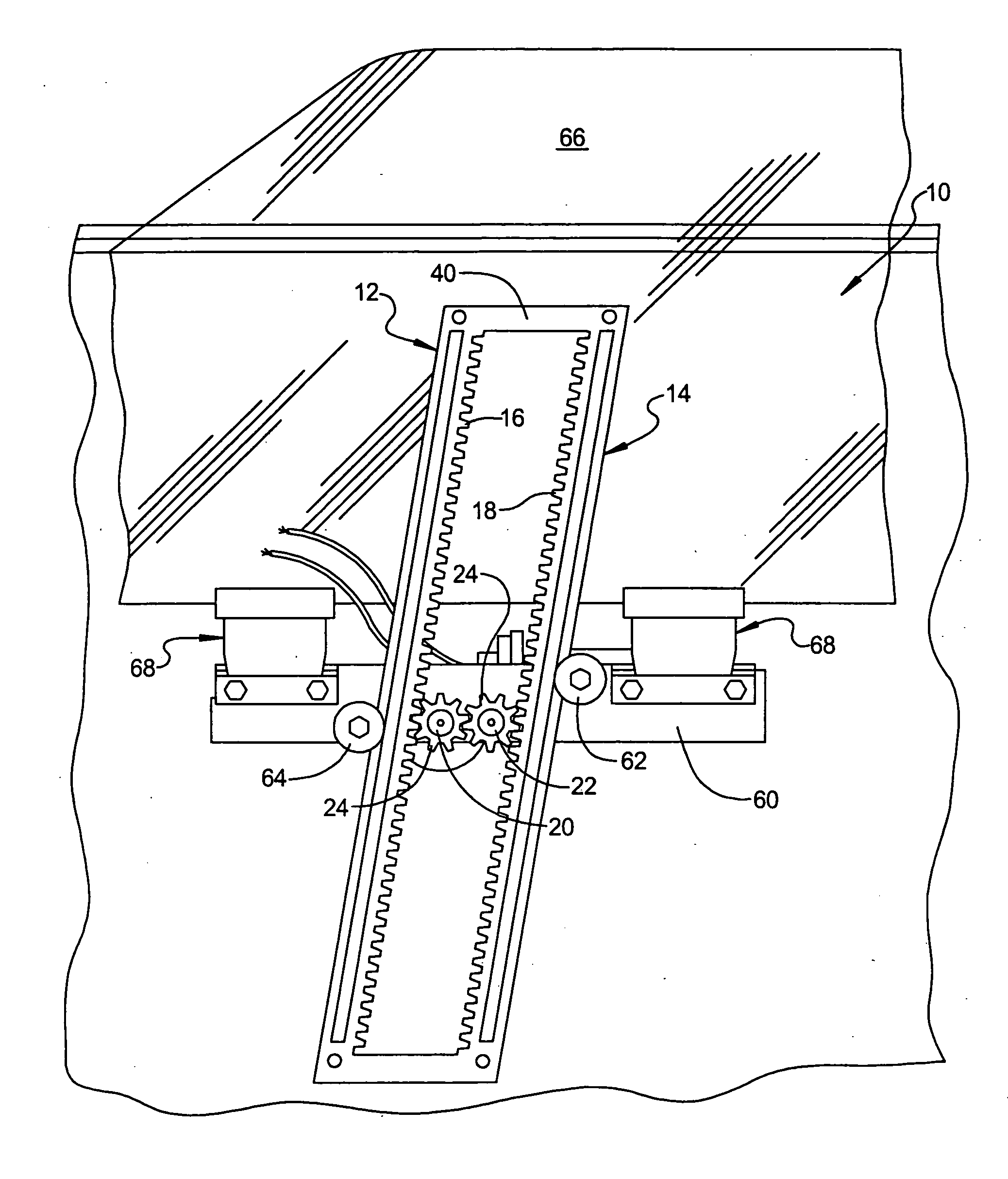
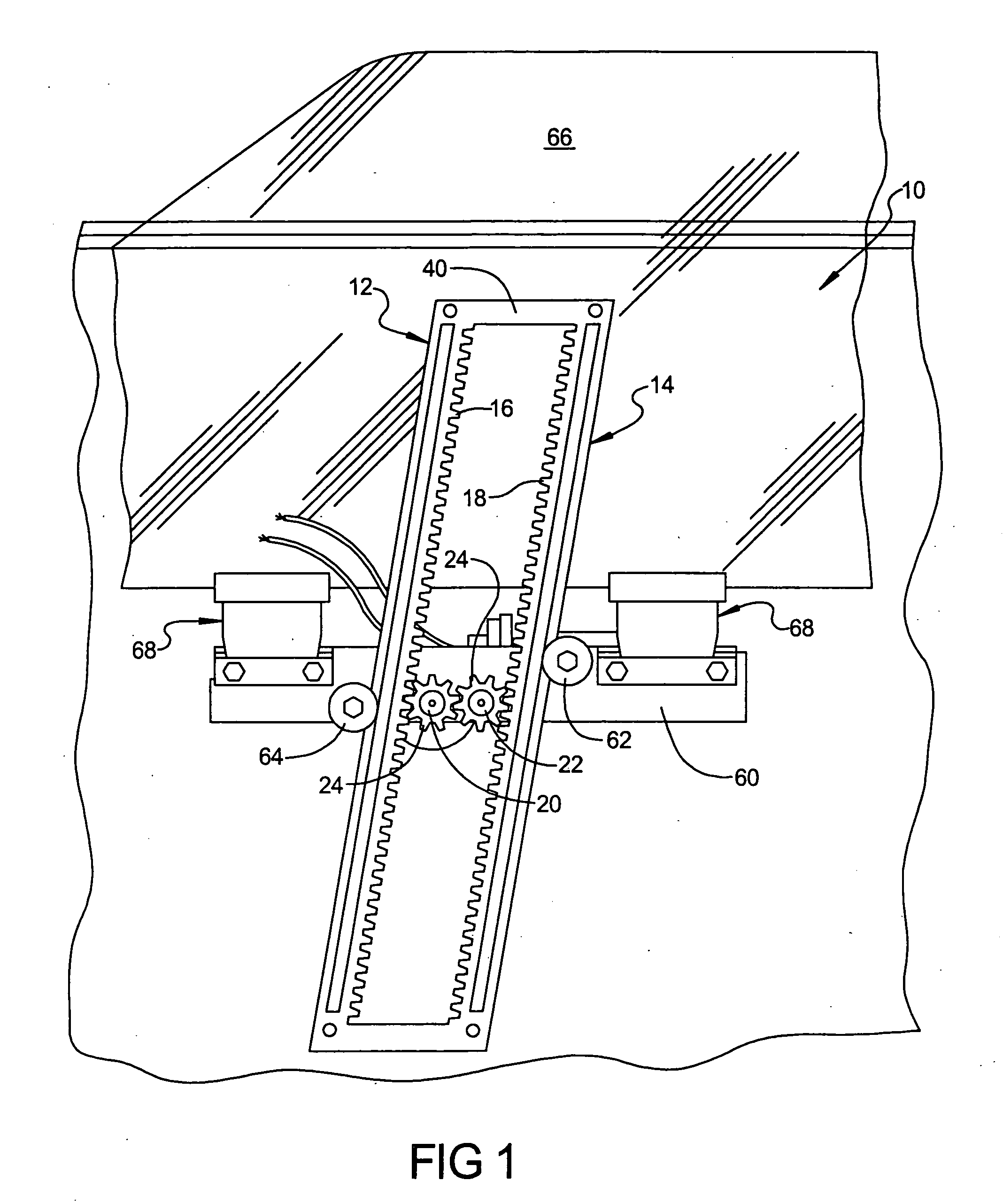
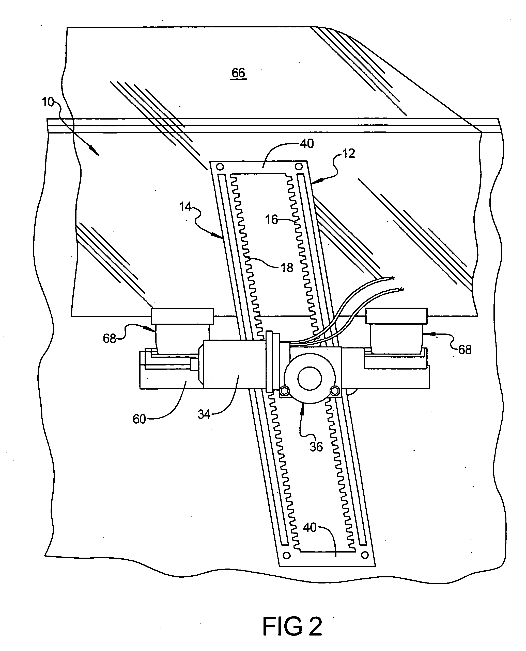
[0017] With reference to FIGS. 1 and 2, a window lift mechanism 10, according to the principles of the present invention, will now be described. The window lift mechanism includes first and second racks 12, 14, each including a row of teeth 16, 18, respectively, which face toward one another. First and second pinion gears 20, 22 are also provided which include teeth 24 in engagement with the teeth 16, 18 on the first and second racks 12, 14. The first and second pinion gears 20, 22 are also in meshing engagement with one another. Specifically, the first and second racks 16, 18 are positioned closely together such that the spacing between the first and second racks 16, 18 is the minimum necessary to accommodate the first and second pinion gears 20, 22.

[0018] The pinion gear 20 is connected to a worm gear 30 as illus...


PUM


Abstract

A window lift mechanism includes a worm/worm gear transmission with an improved transmission housing having a worm gear shaft formed in-situ as well as a pinion gear formed as a unitary member with the worm gear in order to reduce the number of components and improve the assembly process.

Description

FIELD OF THE INVENTION [0001] The present invention generally relates to an apparatus for moving a window into an open or closed position. In particular, the present invention relates to a mechanism for use with an automobile window, wherein the mechanism utilizes an improved dual rack and pinion assembly and method of manufacturing. BACKGROUND AND SUMMARY OF THE INVENTION [0002] Modern automobiles typically include a window lift assembly for raising and lowering windows in the door of the vehicle. A common type of window lift assembly incorporates a “scissor mechanism” or a drum and cable mechanism. A scissor-type system utilizes a series of linkages in a scissor configuration such that as the bottom linkages move apart, the top linkages do as well, resulting in a scissor-like motion. The window is fastened to a bracket connected to a linkage. A motor and gearset drives the scissor mechanism in power operated window mechanisms. [0003] The scissor-type and drum and cable mechanisms ...

Claims


Application Information

Patent Timeline
IPC IPC(8): E05F15/16
CPCE05F11/423E05Y2201/434E05Y2201/716E05Y2201/722E05F15/697E05Y2800/21E05Y2800/29E05Y2900/55E05Y2600/46
Inventor FENELON, PAUL J.
Owner FENELON PAUL J
Why Eureka
Try Eureka