Ultrasonic flowmeter

Active Publication Date: 2007-07-05
ASAHI YUKIZAI KOGYO CO LTD
View PDF14 Cites 14 Cited by
  • Summary
  • Abstract
  • Description
  • Claims
  • Application Information

AI Technical Summary

Benefits of technology

[0009] The object of the present invention is to obviate the above-mentioned problems of the prior arts and to provide a compact and inexpensive ultrasonic flowmeter in which the ultrasonic vibration is efficiently propagated through the fluid in a small-bore pipe and the flow rate can be measured with high accuracy.

Problems solved by technology

This causes a problem that, in the case where the fluid flowing in the flow passage-forming body 100 is a slurry, the slurry tends to be deposited and fixed on the curved portions 104 of the flow passage-forming body 100 and the propagation of the ultrasonic vibration is hampered thereby making accurate flow rate measurement impossible especially in a CMP (chemical mechanical polishing) device in the semiconductor field.
Also, a problem is posed that the curved portions 104 of the flow passage-forming body 110 cause a pressure loss of the fluid in the flow passage-forming body 110, thereby making it impossible to accurately measure the velocity and hence the flow rate.
Further, a problem is posed that the substantially U-shaped pipe path results in a high production cost.
This correspondingly reduces the mounting distance between the detectors 111 and 112, thereby resulting in a problem that the resulting smaller propagation distance and propagation time difference make an accurate measurement, or any measurement, impossible.
However, the use of the resin alone has a disadvantage of an increased attenuation of the ultrasonic vibration.
In addition, the third prior art has problems that the reflection increases the attenuation of the ultrasonic vibration and thereby makes it difficult to measure a micro flow rate and that the mounting of the detectors 114 and 115 is difficult.

Method used


Image

  • Ultrasonic flowmeter
  • Ultrasonic flowmeter
  • Ultrasonic flowmeter

Examples


first embodiment

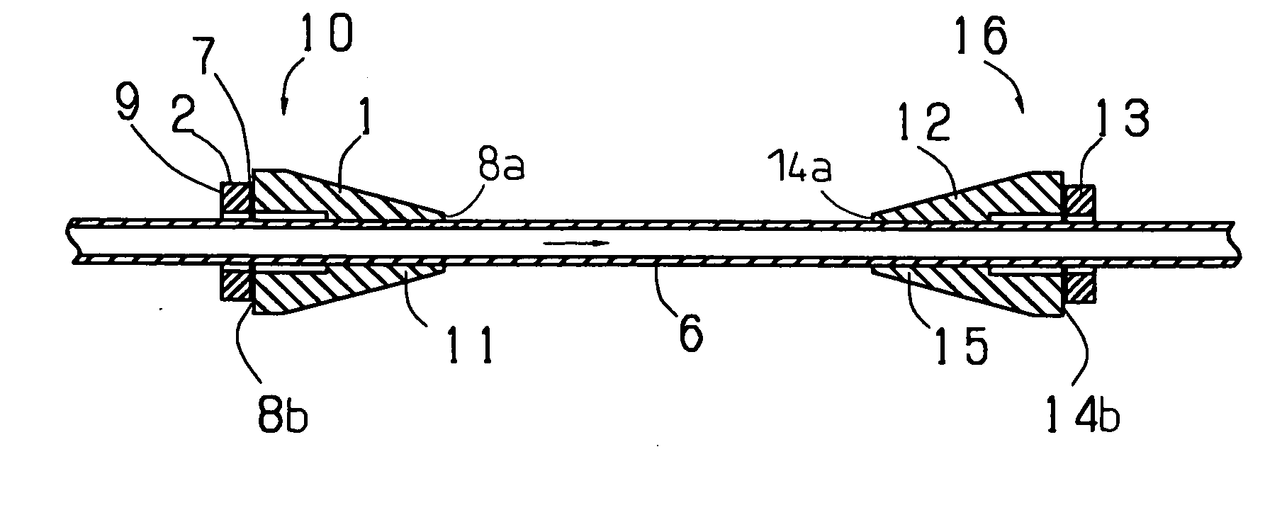
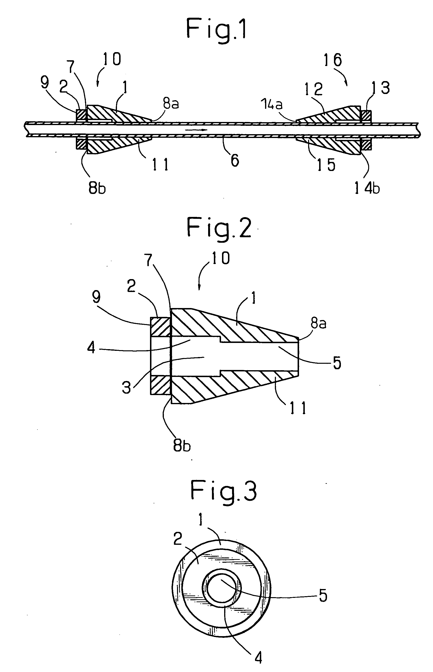
[0037] First, the present invention will be described with reference to FIGS. 1 to 3. Reference numeral “1” designates a transmitting body made of duralumin. The transmitting body 1 has a substantially conical shape and is arranged to surround a measurement pipe 6 made of fluorinated resin. The transmitting body 1 has two axial end surfaces 8a, 8b extending in a direction perpendicular to the axis of the measurement pipe 6. Also, a through-hole 3 including a front through-hole 5 and a rear through-hole 4 is formed at the center of the transmitting body 1. The rear through-hole 4 has an increased diameter larger than that of the front through-hole 5, so that, when the inner peripheral surface of the front through-hole 5 is closely fixed by an adhesive of epoxy resin on the outer peripheral surface of the measurement pipe 6 of fluorinated resin, the inner peripheral surface of the rear through-hole 4 is spaced from the measurement pipe 6. Although duralumin is used as a material for t...

second embodiment

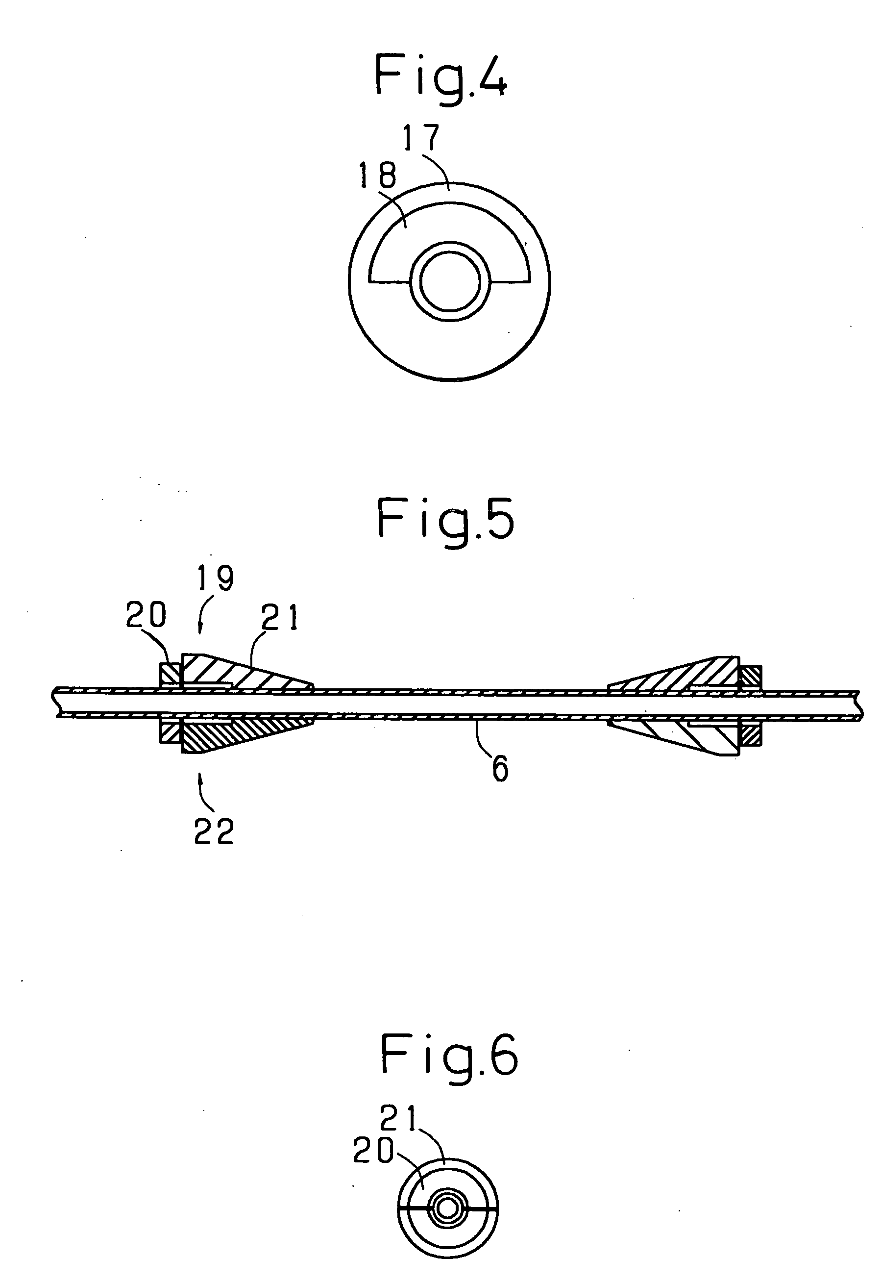
[0045] Next, the present invention will be described with reference to FIGS. 5 and 6.

[0046]FIGS. 5 and 6 show an embodiment in which the ultrasonic transceiver is divided into upper and lower parts. Reference numeral “19” designates an upper half part of the two-part-type ultrasonic transceiver located on the upstream side. The ultrasonic transducer 20 having a substantially semicircular cross section is closely fixed to the substantially semicircular bottom surface of the transmitting body 21, like in the first embodiment, and a pair of half parts, i.e. the ultrasonic transceiver upper half part 19 and the ultrasonic transceiver lower half part 22 having a similar structure, forms an ultrasonic transceiver. It should be noted that only the ultrasonic transceiver upper half part 19 can perform the required functions. In this embodiment, like in the first embodiment, only the inner peripheral surface of the front portion of the through-hole of the transmitting body 21 is in close con...

third embodiment

[0047] Next, the present invention will be described with reference to FIG. 7.

[0048] Reference numeral “23” designates an integrated transmitting body-measurement pipe in which the measurement pipe is integrated with the transmitting body. The ultrasonic transducers 24 and 25 are closely fixed, by a way similar to the first embodiment, to the axial end surfaces of the transmitting body parts 26 and 27 of the integrated transmitting body-measurement pipe 23, and an ultrasonic transceiver is configured of the ultrasonic transducers 24, 25 and the transmitting body parts 26, 27 form ultrasonic transceivers, respectively. At the time of installation, the transmitting bodies, as in the first embodiment, are not required to be closely fixed to the measurement pipe, and the ultrasonic transducers 24 and 25 are closely fixed simply to the axial end surfaces of the transmitting body parts 26 and 27. Therefore, installation can be simplified.


PUM


Abstract

An ultrasonic flowmeter includes two ultrasonic transceivers (10, 16). Each of the ultrasonic transceiver (10, 16) includes a transmitting body (1; 12) fixed to the outer peripheral surface of a measurement pipe (6) through which a fluid to be measured flows so as to surround the measurement pipe (6), and an ultrasonic transducer (2; 13) spaced from the outer peripheral surface of the measurement pipe (6). The transmitting body (1) has axial end surfaces (8a, 8b) perpendicular to the axis of the measurement pipe (6). An axial end surface (7) of the ultrasonic transducer (2) is fixedly secured to the axial end surface (8b) of the transmitting body (1), and the ultrasonic transducer (2) is extended and contracted in the axial direction by applying a voltage between the axial end surfaces (8a, 8b) of the ultrasonic transducer (2).

Description

TECHNICAL FIELD [0001] The present invention relates to an ultrasonic flowmeter, for use in fluid transportation in various industries including the chemical field, the semiconductor manufacture field, the food processing field and the biotechnology field, which propagates an ultrasonic vibration through a fluid and measures the flow velocity and flow rate of the fluid from the difference between the ultrasonic wave propagation time from the upstream side and the ultrasonic wave propagation time from the downstream side of the fluid flow. In particular, the present invention relates to an ultrasonic flowmeter suitable for measuring a micro flow rate and the flow rate of a slurry fluid or especially the CMP slurry fluid used in the semiconductor field. BACKGROUND ART [0002] The conventional ultrasonic flowmeters for measuring a flow rate of a fluid from the difference in ultrasonic wave propagation time are generally classified into three types. [0003]FIG. 9 shows a structure of an u...

Claims


Application Information

Patent Timeline
IPC IPC(8): G01F1/66
CPCG01F1/662G01F1/66
Inventor KAMIMURA, SHINOBU
Owner ASAHI YUKIZAI KOGYO CO LTD
Why Eureka
Try Eureka