Sealable Paint Tray Assembly

a paint tray and assembly technology, applied in the direction of floor cleaners, coatings, carpet cleaners, etc., can solve the problems of adding aggravating to an already difficult task, and achieve the effect of reducing the emissions of volatile organic compounds in paint, without forming skin on paint, and preventing the formation of skin on pain

Inactive Publication Date: 2007-07-05
BILLADO JR HARRY S
View PDF20 Cites 7 Cited by
  • Summary
  • Abstract
  • Description
  • Claims
  • Application Information

AI Technical Summary

Benefits of technology

[0009] A tray assembly including of a paint tray and a matching lid which, when assembled, forms a sealed container effective to maintain paint or other coating material and a paint applicator in a stable condition; that is, for an extended period of time without a skin forming on the paint or allowing the paint applicator to harden while not in use. In addition, the sealed tray assembly may dramatically reduce the volatile organic compound emissions inherent in paint from entering the atmosphere. The seal feature may be formed by a means for locking the lid to the tray by mating projecting flanges on the underside of the lid and the top edge of the tray.
[0010] The tray assembly may include a paint tray having the features above described in combination with an internal applicator rest for maintaining a supplemental applicator, such as a roller assembly, out of contact with the paint in the paint reservoir portion of the tray. The tray may also feature a recess or concave shape at the top of the incline ramp where the roller sleeve portion rests once the end of the roller assembly handle is placed in the internal applicator rest. This concave shape allows the user to fix the roller assembly's sleeve portion within it when the tray is in use and tow the tray around the work area without having to bend down to manually pick up the tray and risk injury to the user and to avoid accidental spillage. To assist the tray tow feature, the front area opposite the paint reservoir or the front legs of the tray, may be formed in an inward or outward curve to enable smooth transport. To further assist the tray tow feature, the back of the tray opposite the front legs and directly under the paint reservoir may include a second pair of legs that are rounded to assist in the smooth transport of the tray across the work area. Further more, the tray's bottom, directly under the paint reservoir may be elevated off the floor to minimize the friction and resistance against the tray assembly when pulled or towed across the floor.
[0011] The lid of the invention could be manufactured by a thermoforming process whereby; minimal material and forming costs are incurred in the manufacturing process. But most likely, the same manufacturing process will be used for forming both the tray and lid which would be an injection molding process to insure a proper fit and seal which would produce a better quality product. In addition, the lid and tray could be constructed so that like parts nest within one another to thereby realize maximum savings in shipping and handling costs when not sold as a kit. When the lid is sealed, the lid's surface just over the paint reservoir portion of the tray may be concaved inward in two halves stopping at a point just above the maximum paint fill line located on the tray in the paint reservoir portion. These two half portion of the lid may be separated by the location of the roller assembly handle when placed in the internal applicator rest. When the lid is sealed on the tray with the roller assembly in its proper location within the tray, the front portion of the lid's surface just over the roller sleeve portion of the roller assembly is convex in shape and forms closely around the roller sleeve portion. When the lid is properly sealed on the tray, and the roller assembly is properly located in the internal applicator rest, the above described lid closely mirrors the internal paint reservoir, and inclined ramp of the tray and the inclusive paint roller assembly. The purpose of this is to displace as much air within the sealed tray assembly to maximize and extend the period of time without a skin forming on the paint and the hardening of the paint roller sleeve portion of the roller assembly.

Problems solved by technology

Accidents in this regard occur far too often and add aggravation to an already difficult task.

Method used


Image

  • Sealable Paint Tray Assembly
  • Sealable Paint Tray Assembly
  • Sealable Paint Tray Assembly

Examples


Embodiment Construction

[0025] In the following description of a specific embodiment like reference numerals will be used to refer to like or similar parts from Figure to Figure in the drawing.

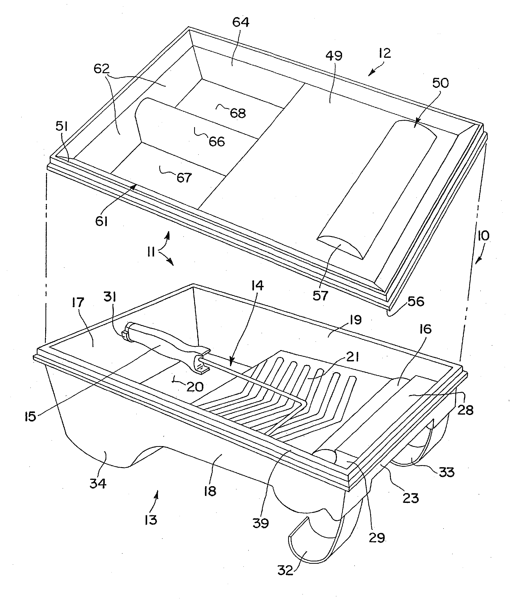
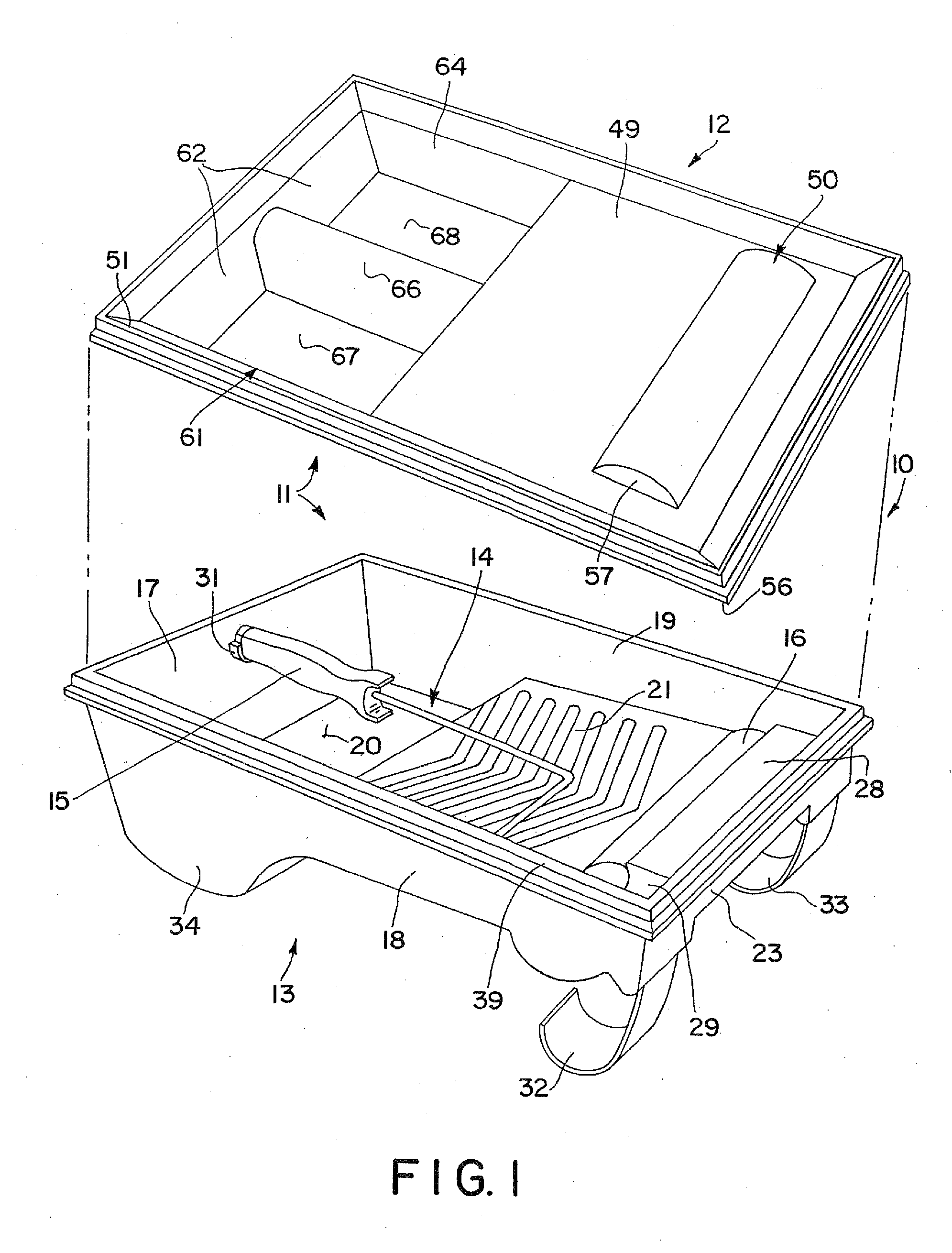
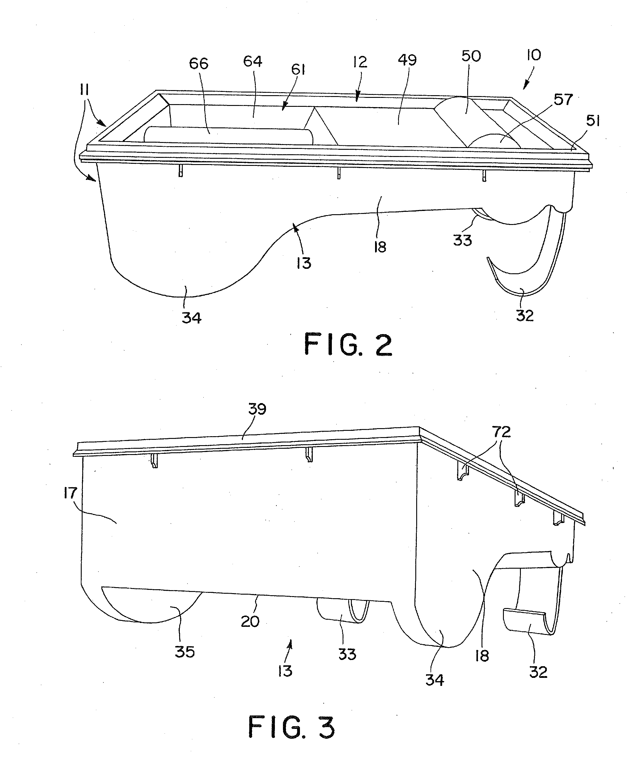
[0026] Referring first to FIG. 1, the paint kit of this invention is illustrated generally at 10 in an exploded, disassembled condition. The paint kit 10 includes a tray assembly indicated generally at 11, the tray assembly consisting of a lid indicated generally at 12 and a tray body indicated generally at 13. The kit 10, in addition to the tray assembly 11, also includes a paint applicator indicated generally at 14, here a roller assembly. The roller assembly 14 may include a handle 15 and a sleeve portion 16. In FIG. 1 the lid and tray are shown in an unassembled, exploded condition whereas in FIG. 2 the lid and tray are shown sealed and assembled.

[0027] Tray body 13 of tray assembly 11 includes rear wall 17, left wall 18, right wall 19, and bottom wall 20. The upper peripheral co-planer edges of rear wall 17, l...


PUM


Abstract

A paint tray system including a paint tray and a lid that may be sealed to the paint tray in a generally airtight manner. The shape of the lid corresponds to the interior of the paint tray so that the volume of air sealed in the paint try by the lid is minimized. The underside of the lid may also include a recess that may receive a paint applicator between the paint tray and the lid. The paint tray may also include an applicator rest for holding a paint roller in the paint tray while keeping the handle out of a paint reservoir.

Description

CROSS-REFERENCE TO RELATED APPLICATIONS [0001] This is a divisional of U.S. patent application Ser. No. 10 / 889,241, filed Jul. 12, 2004, which is a continuation application of International Application No. PCT / US03 / 00980 filed Jan. 14, 2003, and claims benefit of U.S. provisional patent application Ser. No. 60 / 349,009, filed Jan. 14, 2002, the teachings of which applications are incorporated herein by reference.FIELD OF INVENTION [0002] This invention relates to plastic and metal paint tray assemblies and paint kits, more particularly to a paint tray assembly that has a sealable lid and a paint kit with a sealable lid and paint applicator such as a roller assembly. BACKGROUND [0003] This invention relates generally to sealable paint tray assemblies and paint kits, more specifically to a combination wet architectural coating and wet coating applicator storage container, dry storage container, and dry package assembly for sealable paint tray assemblies or paint kits. For convenience o...

Claims


Application Information

Patent Timeline
Patent Type & Authority Applications(United States)
IPC IPC(8): B05C21/00B44D3/12B05C17/02B65D1/34
CPCB05C17/0245B44D3/128B44D3/127B44D3/121
Inventor BILLADO, HARRY S. JR.
Owner BILLADO JR HARRY S
Why Eureka
Try Eureka