Apparatus and method for detecting phase currents of inverter

a technology of inverter and phase current, which is applied in the direction of dc-ac conversion without reversal, process and machine control, instruments, etc., can solve the problems of inverter components being broken, sensors themselves being manufactured at very high costs, and damage to load

Active Publication Date: 2007-07-05
LS IND SYETEMS CO LTD
View PDF2 Cites 24 Cited by
  • Summary
  • Abstract
  • Description
  • Claims
  • Application Information

AI Technical Summary

Benefits of technology

[0028]The above object of the present invention is substantially realized by providing an apparatus for detecting phase currents of an inverter comprising: a switch section for converting a direct current power into an alternating current power and providing the alternating current power to a load as a plurality of upper switching elements and lower switching elements are turned-on according to a plurality of pulse width modulation signals; a plurality of current detecting resistors coupled between the plurality of lower switching elements and a ground, respectively; a plurality of analog/digital converters for converting voltages of the plurality of current detecting resistors into digital signals; a triangular wave generator for generating a triangular wave having a predetermined time period; a current detection controller for generating three-phase sine wave voltages, for comparing the generated three-phase sine wave voltage with a reference threshold voltage, and for varying the three-phase sine wave voltage according to the compared result to control a detection of the phase currents; a pulse width modulation signal generator for comparing the three-phase sine wave voltages from the current detection controller with a voltage of the triangula

Problems solved by technology

When such an inverter supplies an over current to the load, the load is damaged, and components constituting the inverter are also broken due to the over current.
The first method has a disadvantage that the sensors themselves are manufactured at very high cost.
The insulation means is expensive and a circuit is complex in construction.
However, in

Method used


Image

  • Apparatus and method for detecting phase currents of inverter
  • Apparatus and method for detecting phase currents of inverter
  • Apparatus and method for detecting phase currents of inverter

Examples


Embodiment Construction

[0035]An apparatus and a method for detecting phase currents of an inverter according to a preferable embodiment of the present invention will now be described with reference to the accompanying drawings, in which preferred embodiments of the invention are shown. The present invention now will be described more fully hereinafter with reference to the accompanying drawings, in which embodiments of the invention are shown. However, this invention should not be construed as limited to the embodiments set forth herein. Rather, these embodiments are provided so that this disclosure will be thorough and complete, and will fully convey the scope of the invention to those skilled in the art. Like numbers refer to like elements.

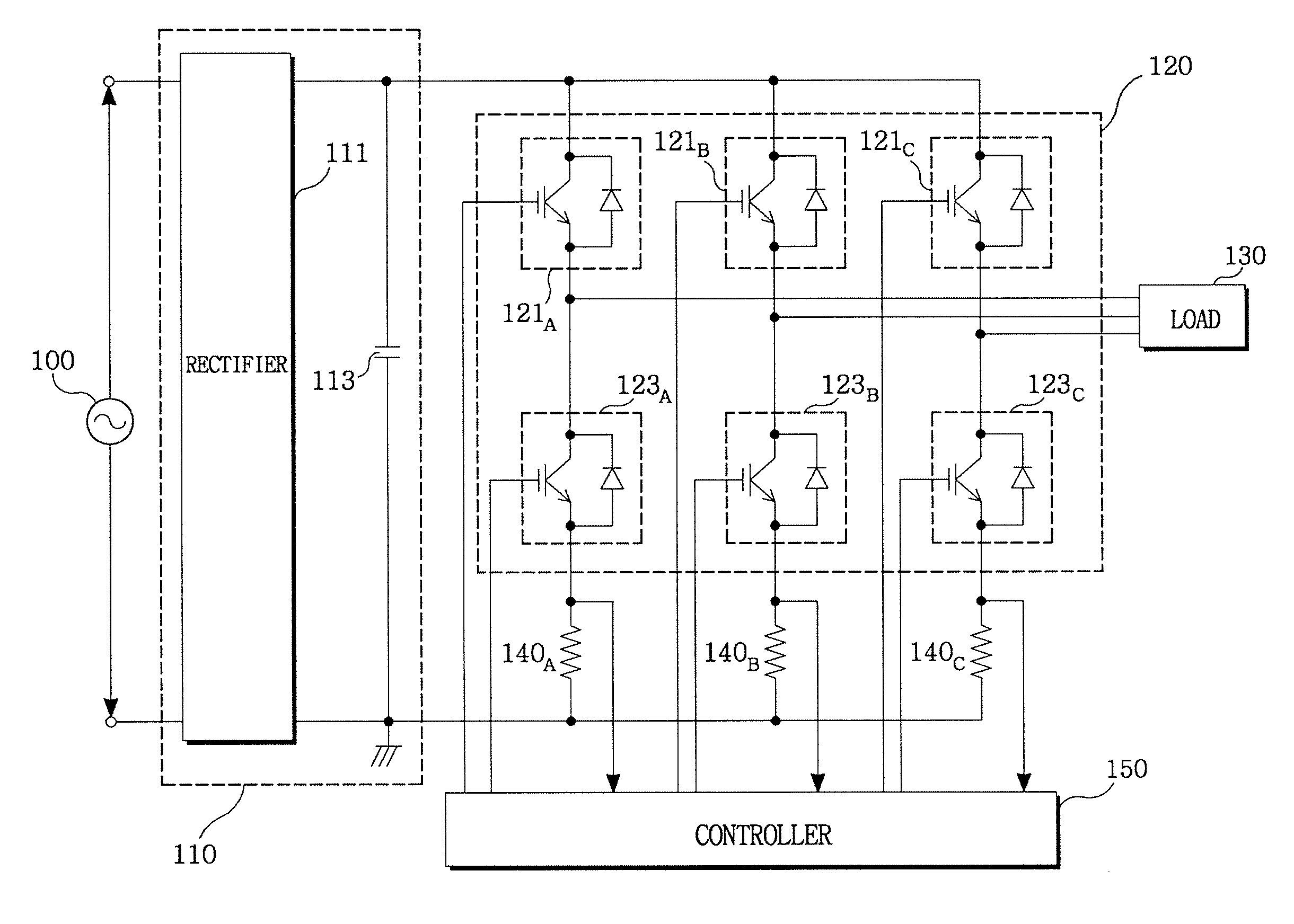
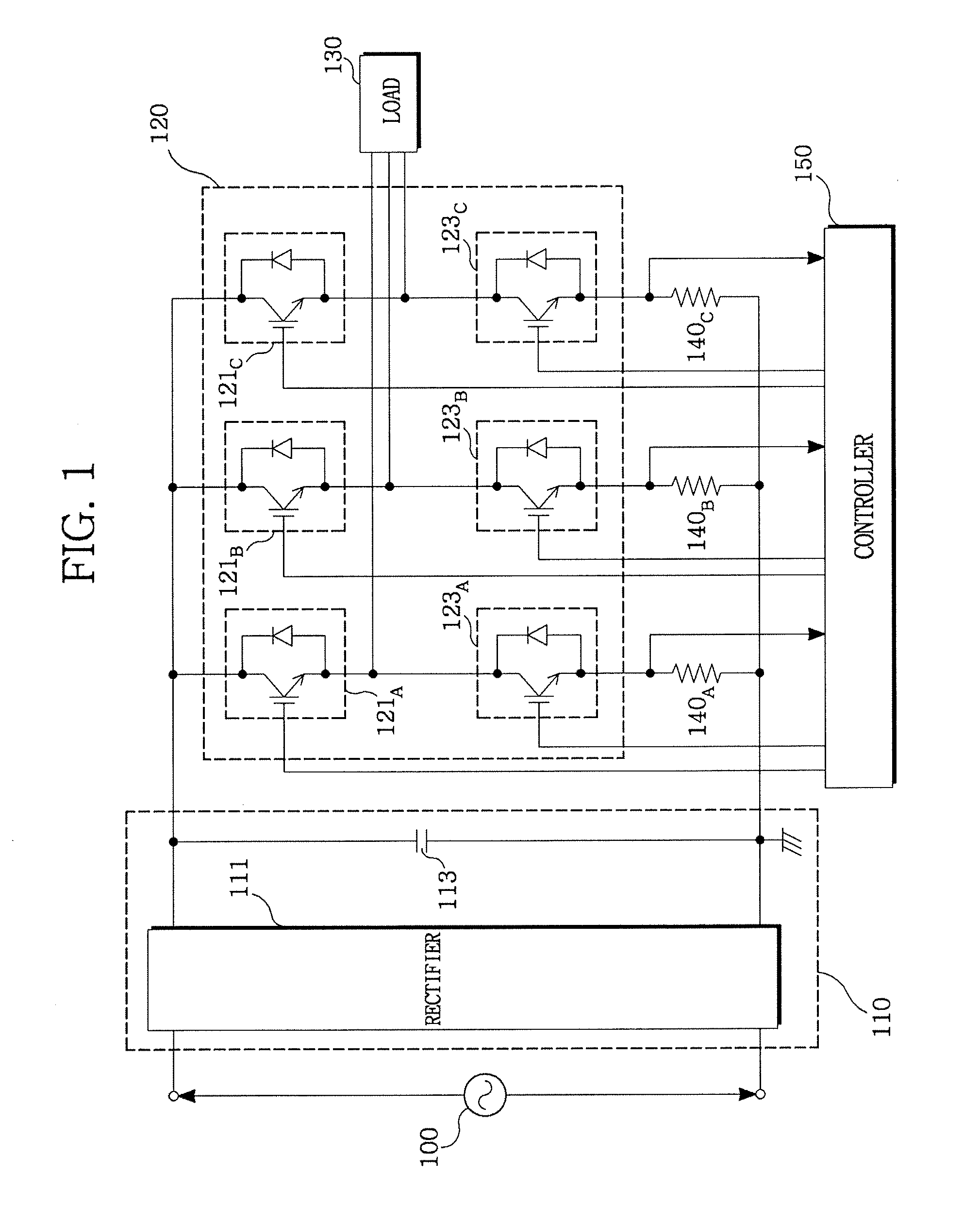
[0036]FIG. 1 is a block diagram showing an inverter according to an embodiment of the present invention. Reference numeral 100 represents an alternating current power source. Reference numeral 110 represents a power converter an AC power supplied from the AC power sou...


PUM


Abstract

The present invention previously sets a threshold voltage, compares the set threshold voltage with a reference voltage, and judges whether a minimal pulse width of a PWM signal is obtained. When a pulse width of one PWM signal is equal to or greater than the minimal pulse width, but each pulse width of two PWM signals is less than the minimal pulse width, a sine wave voltage corresponding to one of the two PWM signals less than the minimal pulse width is varied to a threshold voltage to detect two phase currents, and a remaining one phase current is calculated based on the two detected phase currents. After the phase current was detected by varying the threshold voltage, a level difference between an original sine wave voltage and the threshold voltage is set as a compensation voltage, and the sine wave voltage is compensated by the compensation voltage.

Description

CLAIM FOR PRIORITY[0001]This application is based on and claims priority to Korean Patent Application No. 10-2005-00136041 filed on Dec. 30, 2005 in the Korean Intellectual Property Office (KIPO), the entire contents of which are hereby incorporated by reference.BACKGROUND OF THE INVENTION[0002]1. Field of the Invention[0003]The present invention relates to an apparatus and a method for detecting phase currents of an inverter, and more particularly, to an apparatus and a method for detecting phase currents of an inverter, which detect three-phase currents of an alternating current (hereinafter referred to as ‘AC’) power that an inverter outputs to a load.[0004]2. Description of the Related Art[0005]In general, an inverter has been widely used in order to control a load such as an induction motor with precision. The inverter generates a pulse width modulation (referred to as ‘PWM’ hereinafter) signal, and selectively switches a plurality of switching elements by the generated PWM sig...

Claims


Application Information

Patent Timeline
IPC IPC(8): G01R31/08
CPCH02P23/0036H02P2207/01H02P2205/01H02P23/0004H02M7/48H02P27/06
Inventor LEE, KYUNG JOO
Owner LS IND SYETEMS CO LTD
Why Eureka
Try Eureka