Phase Frequency Detectors Generating Minimum Pulse Widths

Inactive Publication Date: 2008-10-09
ALTERA CORP
View PDF3 Cites 8 Cited by
  • Summary
  • Abstract
  • Description
  • Claims
  • Application Information

AI Technical Summary

Benefits of technology

[0007]A phase frequency detector compares a reference clock signal to a feedback clock signal to gene

Problems solved by technology

When the PFD does not generate pulses in lock mode, the charge pump does not provide charge to the loop filter.
As a result, charge leaks away from the loop filter, and the control voltage on the loop filter drifts away from a stable value.
If the minimum pulse of the PFD is too narrow, the PLL has a larger static phase error.

Method used


Image

  • Phase Frequency Detectors Generating Minimum Pulse Widths
  • Phase Frequency Detectors Generating Minimum Pulse Widths
  • Phase Frequency Detectors Generating Minimum Pulse Widths

Examples


Embodiment Construction

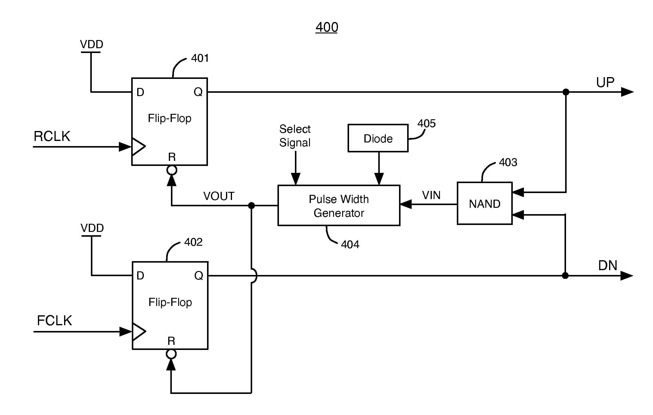
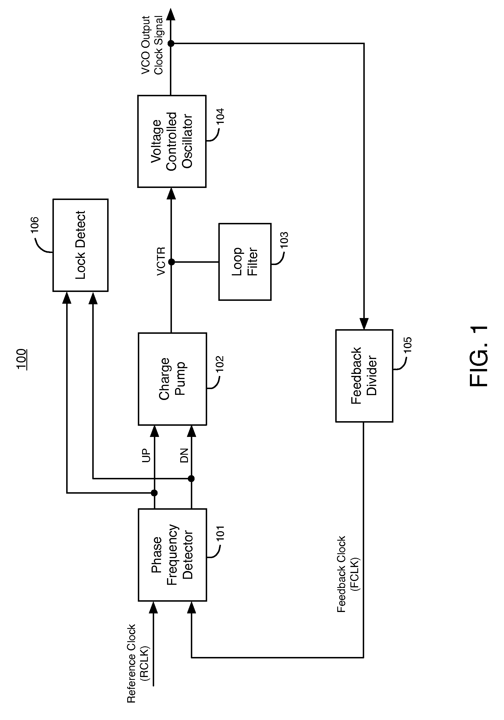
[0021]FIG. 1 illustrates an example of a phase-locked loop (PLL) 100 that can include embodiments of the present invention. PLL 100 includes phase frequency detector (PFD) 101, charge pump (CP) 102, loop filter (LF) 103, voltage-controlled oscillator (VCO) 104, feedback divider 105, and lock detect circuit (LD) 106. VCO 104 generates a VCO output clock signal. Feedback divider 105 includes a counter circuit that divides the frequency of the VCO output clock signal to generate a feedback clock signal (FCLK).

[0022]PFD 101 compares the phase and frequency of the reference clock signal (RCLK) to the phase and frequency of the feedback clock signal (FCLK). PFD 101 varies the width of pulses in its UP and DN output signals in response to differences in the phase and frequency of RCLK and FCLK, until the phase and frequency of FCLK and RCLK are the same. Typically, a pulse refers to a period of time when a digital signal is in a logic high state. However, according to alternative embodimen...


PUM


Abstract

A phase frequency detector compares a reference clock signal to a feedback clock signal to generate pulses in one or more output signals. The one or more output signals have a minimum pulse width. The phase frequency detector has a temperature sensing circuit. The phase frequency detector adjusts the minimum pulse width of the one or more output signals using the temperature sensing circuit to compensate for variations in the temperature of the phase frequency detector.

Description

BACKGROUND OF THE INVENTION[0001]The present invention relates to electronic circuits, and more particularly, to phase frequency detectors that generate signals having minimum pulse widths.[0002]A phase-locked loop (PLL) is an electronic circuit with a voltage or current driven oscillator that is constantly adjusted to match in phase (and thus lock on) the frequency of a reference clock signal. In addition to stabilizing a particular communications channel by keeping it set to a particular frequency, a PLL can be used to generate a signal, modulate or demodulate a signal, reconstitute a signal with less noise, or multiply or divide a frequency.[0003]A PLL typically includes a phase frequency detector (PFD), a charge pump, and a loop filter in addition to the oscillator. The PFD generates pulses in it output signals in response to the difference between the phase and frequency of a reference clock signal and a feedback clock signal from the oscillator. When the phase and frequency of...

Claims


Application Information

Patent Timeline
IPC IPC(8): H03D13/00
CPCH03D13/004
Inventor HOANG, TIM TRISHUMARAYEV, SERGEYCHANG, WANLI
Owner ALTERA CORP
Why Eureka
Try Eureka