Voltage conversion device

a voltage conversion device and voltage technology, applied in the direction of power conversion systems, dc-dc conversion, instruments, etc., can solve the problems of inability to obtain the desired output, inability to maintain the output, and heat generation, and achieve the effect of prolonging the switching cycle, increasing the size of the smoothing inductance, and ensuring the minimum pulse width

Inactive Publication Date: 2022-06-09
YAZAKI CORP
View PDF0 Cites 0 Cited by
  • Summary
  • Abstract
  • Description
  • Claims
  • Application Information

AI Technical Summary

Benefits of technology

[0007]Therefore, when a switching frequency is lowered as a whole, that is, a switching cycle is prolonged, the minimum pulse width is easily ensured even if one of the duty ratios D1, D2 becomes small. However, in this case, it is necessary to store a large amount of energy in a smoothing inductance in response to a long cycle, resulting in an increase in a size of the smoothing inductance.
[0008]The present invention has been made to solve such related-art problems, and an object thereof is to provide a voltage conversion device capable of ensuring a minimum pulse width, suppressing heat generation, easily obtaining a desired output, and preventing an increase in a size of a smoothing inductance.

Problems solved by technology

When an attempt is made to perform switching with a pulse width smaller than the minimum pulse width at the time of switching, the switching element is driven without being completely turned on, so that heat generation becomes a problem and an output cannot be maintained.
However, when the difference between the output currents Io1, Io2 is large, one of the duty ratios D1, D2 becomes small, so that the minimum pulse width cannot be ensured, which causes a problem of heat generation and makes it impossible to obtain a desired output.
However, in this case, it is necessary to store a large amount of energy in a smoothing inductance in response to a long cycle, resulting in an increase in a size of the smoothing inductance.

Method used


Image

  • Voltage conversion device
  • Voltage conversion device
  • Voltage conversion device

Examples


Embodiment Construction

[0015]Hereinafter, the present invention will be described in accordance with a preferred embodiment. The present invention is not limited to the embodiment to be described below, and can be changed as appropriate without departing from the scope of the present invention. In the embodiment described below, some configurations are not shown or described, but it goes without saying that a known or well-known technique is applied as appropriate to details of an omitted technique within a range in which no contradiction occurs to contents described below.

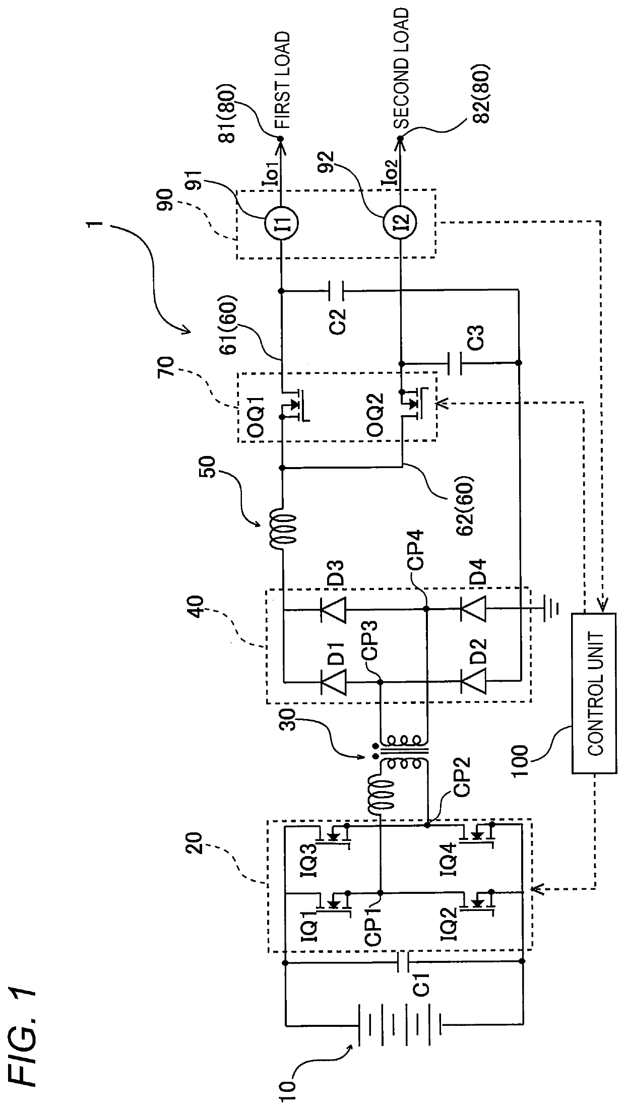
[0016]FIG. 1 is a configuration diagram of a voltage conversion device according to an embodiment of the present invention. A voltage conversion device 1 shown in FIG. 1 uses a voltage from a high-voltage power supply 10 as an input voltage and outputs a plurality of (two) different desired output voltages, and includes the power supply 10, a full bridge circuit 20, a transformer 30, a rectifier circuit 40, a smoothing inductance 50, a ...


PUM


Abstract

A voltage conversion device includes input-side switching elements provided on an input side of a smoothing inductance and configured to perform switching, first and second power supply lines provided on an output side of the smoothing inductance and configured to respectively supply power to a first load and a second load, output-side switching elements respectively provided on the first and second power supply lines, and a control unit configured to perform on/off control on the input-side switching elements and the output-side switching elements. The control unit performs the on/off control by setting switching frequencies of the output-side switching elements to be lower than switching frequencies of the input-side switching elements.

Description

CROSS-REFERENCE TO RELATED APPLICATIONS[0001]This application is based on and claims priority under 35 USC 119 from Japanese Patent Application No. 2020-200809 filed on Dec. 3, 2020, the contents of which are incorporated herein by reference.TECHNICAL FIELD[0002]The present invention relates to a voltage conversion device.BACKGROUND ART[0003]In related-art, a voltage conversion device having a full bridge circuit that supplies power to a load after voltage conversion has been proposed (for example, see Patent Literature 1). As such a voltage conversion device, a single-inductor multiple-output (SMO) type voltage conversion device has been proposed in order to obtain a plurality of outputs.CITATION LISTPatent Literature[0004]Patent Literature 1: JP-2020-080625-ASUMMARY OF INVENTION[0005]When two output currents Io1, Io2 are obtained as in a SIMO type voltage conversion device disclosed in Patent Literature 1, a duty ratio D1 of a first switching element on a secondary side is D1=Io1 / ...

Claims


Application Information

Patent Timeline
Patent Type & Authority Applications(United States)
IPC IPC(8): H02M3/335H02M1/00
CPCH02M3/33573H02M1/0009H02M3/3353H02M1/14H02M1/009H02M1/007H02M3/33561H02M3/158H02M3/1582
Inventor KANDA, KEISUKEITO, SATOSHIYOSHIMITSU, SHOTA
Owner YAZAKI CORP
Why Eureka
Try Eureka