Switching amplifier

a switching amplifier and amplifier technology, applied in the field of switching amplifiers, can solve the problems of reducing the signal-to-noise ratio of the audio frequency range with respect to which the analog audio signal is processed, reducing the power efficiency of the switching amplifier, and increasing the radiated noise. the effect of reducing the delay time and simple circuit design

Inactive Publication Date: 2006-10-19
SHARP KK
View PDF6 Cites 4 Cited by
  • Summary
  • Abstract
  • Description
  • Claims
  • Application Information

AI Technical Summary

Benefits of technology

[0020] The above switching amplifier may be so configured that the delay section includes an input terminal, a plurality of delay elements, and an output terminal, that the plurality of delay elements produce fixed delay times respectively, that the plurality of delay elements are cascade-connected, and that the delay time of the delay section is varied by varying interconnection among the input terminal, the plurality of delay elements, and the output terminal. With this configuration, the delay section for varying the delay time can be realized with a simple circuit design.
[0021] The switching amplifier of any of the configurations described above may be further provided with a delay time controller for controlling the delay time of the delay section, so that, as a result of the delay time controller controlling the delay time of the delay section, the minimum pulse width of the pulse signal outputted from the pulse amplifier is controlled, and thereby the number of times that the pulse amplifier switches per unit time is controlled. Alternatively, the switching amplifier may be further provided with a delay time controller for controlling a delay time of the delay section, so that, as a result of the delay time controller controlling the delay time of the delay section, the minimum pulse width of the pulse signal outputted from the pulse amplifier is controlled, and thereby the amount of information that the switching amplifier outputs per unit time is controlled.
[0022] With the former control, the delay time controller can control the delay section to increase the delay time it produces. This makes it possible, without changing the sampling frequency of the delta-sigma modulation circuit, to increase the minimum pulse width of the pulse signal outputted from the pulse amplifier, and thereby to reduce the number of times that the pulse amplifier switches per unit time. Thus, it is possible, without changing the sampling frequency of the delta-sigma modulation circuit, to achieve enhanced power efficiency. Since the number of times that the pulse amplifier switches per unit time is reduced without lowering the sampling frequency of the delta-sigma modulation circuit, no such problems occur as a narrowing of the noise shaping frequency range and, in a case where the input signal is an analog audio signal, a reduction in the SN (signal-to-noise) ratio in the audible range in which the analog audio signal is processed.
[0023] With the latter control, the delay time controller can control the delay section to decrease the delay time it produces. This makes it possible, without changing the sampling frequency of the delta-sigma modulation circuit, to decrease the minimum pulse width of the pulse signal outputted from the pulse amplifier, and thereby to increase the amount of information that the switching amplifier outputs per unit time. Thus, it is possible, without changing the sampling frequency of the delta-sigma modulation circuit, to achieve a wide dynamic range and low residual noise. Since the amount of information that the switching amplifier outputs per unit time is increased without raising the sampling frequency of the delta-sigma modulation circuit, no such problems occur as an increase in radiated noise, as a result of raising the master clock frequency with a view to raising the sampling frequency of the delta-sigma modulation circuit, and the resulting increase in cost for measures against EMI (electromagnetic interference). Furthermore, in a case where the input signal is an analog audio signal, by increasing the amount of information that the switching amplifier outputs per unit time, it is possible to enhance the resolution and naturalness of sound.
[0024] The switching amplifier of any of the configurations described above may be further provided with a converter for converting an output signal of the pulse amplifier into an analog signal. With this configuration, it is possible to yield an analog output.
[0025] The switching amplifier of any of the configurations described above may be further provided with a feedback section for feeding a signal based on the output signal of the pulse amplifier back to the delta-sigma modulation circuit. With this configuration, it is possible to improve the distortion factor and the SN ratio of the pulse amplifier itself.

Problems solved by technology

This switching loss lowers the power efficiency of the switching amplifier shown in FIG. 7.
However, a low sampling frequency of the delta-sigma modulation circuit 3 disadvantageously narrows the noise shaping frequency range or when the input signal SIN is an analog audio signal, disadvantageously reduces the SN ratio (signal-to-noise ratio) of the audio frequency range with respect to which the analog audio signal is processed.
So as to raise the sampling frequency of the delta-sigma modulation circuit 3, however, the master clock frequency needs to be raised, and this increases radiated noise.
Hence, extra cost for measures against EMI (electromagnetic interference) is required, which is disadvantageous.

Method used


Image

  • Switching amplifier
  • Switching amplifier
  • Switching amplifier

Examples


Embodiment Construction

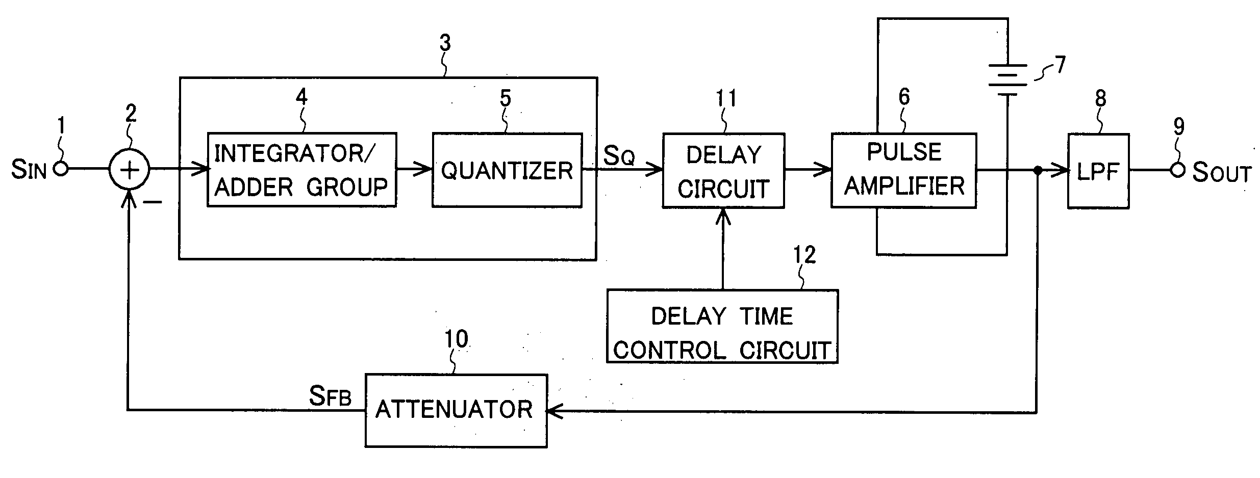
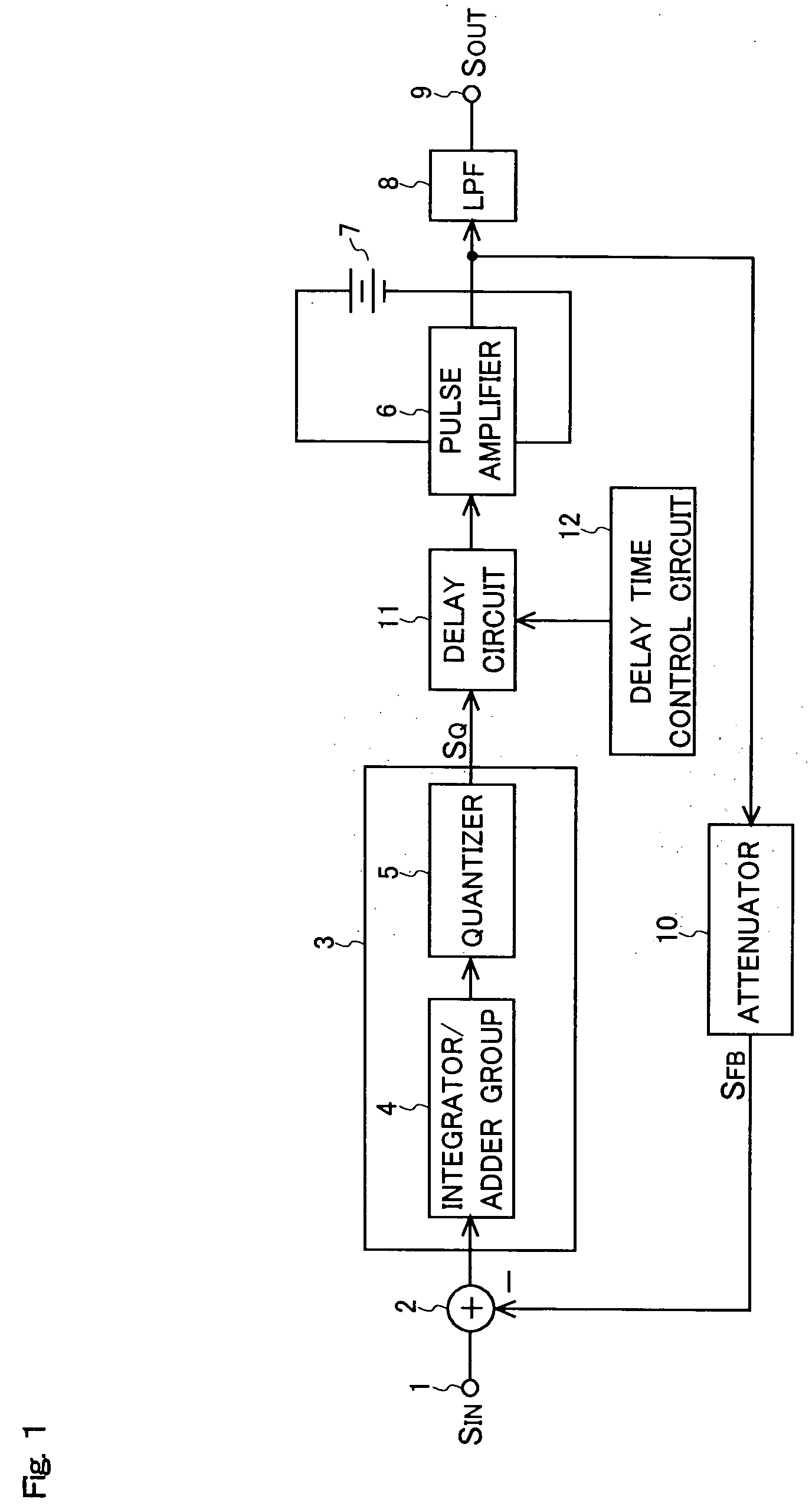
[0033] Hereinafter, embodiments of the present invention will be described with reference to the accompanying drawings. An example of the electrical configuration of a switching amplifier according to the present invention is shown in FIG. 1. In FIG. 1, such parts as are found also in FIG. 7 are identified with common reference numerals and symbols.

[0034] The switching amplifier shown in FIG. 1 is a switching amplifier that performs power amplification by using a one-bit signal obtained by delta-sigma modulation, and includes: an input terminal 1; an adder 2; a delta-sigma modulation circuit 3; a pulse amplifier 6 to which a constant voltage is applied from a constant voltage source 7; a low-pass filter 8; an output terminal 9; an attenuator 10; a delay circuit 11; and a delay time control circuit 12. The delta-sigma modulation circuit 3 includes: an integrator / adder group 4 including a plurality of cascade-connected integrators that integrate one input signal after another and an ...


PUM


Abstract

A switching amplifier of the present invention includes a delta-sigma modulation circuit for processing an input signal by delta-sigma modulation to output a one-bit signal, a delay circuit for delaying the one-bit signal, and a pulse amplifier having a switching device that switches the switching device according to the signal outputted from the delay circuit to perform pulse amplification of the signal outputted from the delay section. The delay time of the delay circuit is variable. With this configuration, enhanced performance is obtained without changing the sampling frequency of the delta-sigma modulation circuit.

Description

[0001] This nonprovisional application claims priority under 35 U.S.C. § 119(a) on Patent Application No. 2005-116730 filed in Japan on Apr. 14, 2005, the entire contents of which are hereby incorporated by reference. BACKGROUND OF THE INVENTION [0002] 1. Field of the Invention [0003] The present invention relates to a switching amplifier that performs pulse amplification by using, as a switching control signal, a quantized signal obtained by processing an analog signal or a one-bit signal by delta-sigma modulation. [0004] 2. Description of Related Art [0005] A one-bit signal obtained by processing an analog signal or a one-bit signal by delta-sigma modulation is advantageous in that it allows a frequency response to suit an audio source or the like, for example, by widening the effective frequency range or the dynamic range simply through appropriate selection of the constants of an integrator and an adder provided in the delta-sigma modulation circuit that performs the delta-signa...

Claims


Application Information

Patent Timeline
Patent Type & Authority Applications(United States)
IPC IPC(8): H03M3/00
CPCH03F3/217H03F2200/03H03M3/502H03M3/37H03F2200/331
Inventor KISHIDA, MASAHIRO
Owner SHARP KK
Why Eureka
Try Eureka