Self-oscillating modulator with improved synchronisation and pwm cycle constraints

a self-oscillating, modulator technology, applied in pulse duration/width modulation, electrical apparatus, pulse technique, etc., can solve the problems of increasing the problem of cross-talk between other system components, affecting the operation of the amplifier at the same time, and the disadvantage of the self-oscillating pwm amplifier

Inactive Publication Date: 2009-10-08
TC-GROUP
View PDF7 Cites 1 Cited by
  • Summary
  • Abstract
  • Description
  • Claims
  • Application Information

AI Technical Summary

Benefits of technology

[0042]When said synchronization signal 17 is applied within the loop of the self-oscillating modulator 2 by providing it as reference signal to a modulator 12 of said self-oscillating modulator 2, an advantageous embodiment of the present invention has been obtained.
[0043]When said synchroniza...

Problems solved by technology

Known self-oscillating PWM amplifiers do, however, also suffer from a disadvantage, as their switch frequency fluctuates with the level of the input signal.
Among other things, this problem complicates operating more amplifiers simultaneously, e.g. in a multi-channel application, due to cross-talk, and moreover, it also increases problems with cross-talk to other system components such as, e.g., converters, phase-locked-loops, tuners, etc.
Reference signals of larger amplitudes may be able to reduce the fluctuatio...

Method used


Image

  • Self-oscillating modulator with improved synchronisation and pwm cycle constraints
  • Self-oscillating modulator with improved synchronisation and pwm cycle constraints
  • Self-oscillating modulator with improved synchronisation and pwm cycle constraints

Examples


Embodiment Construction

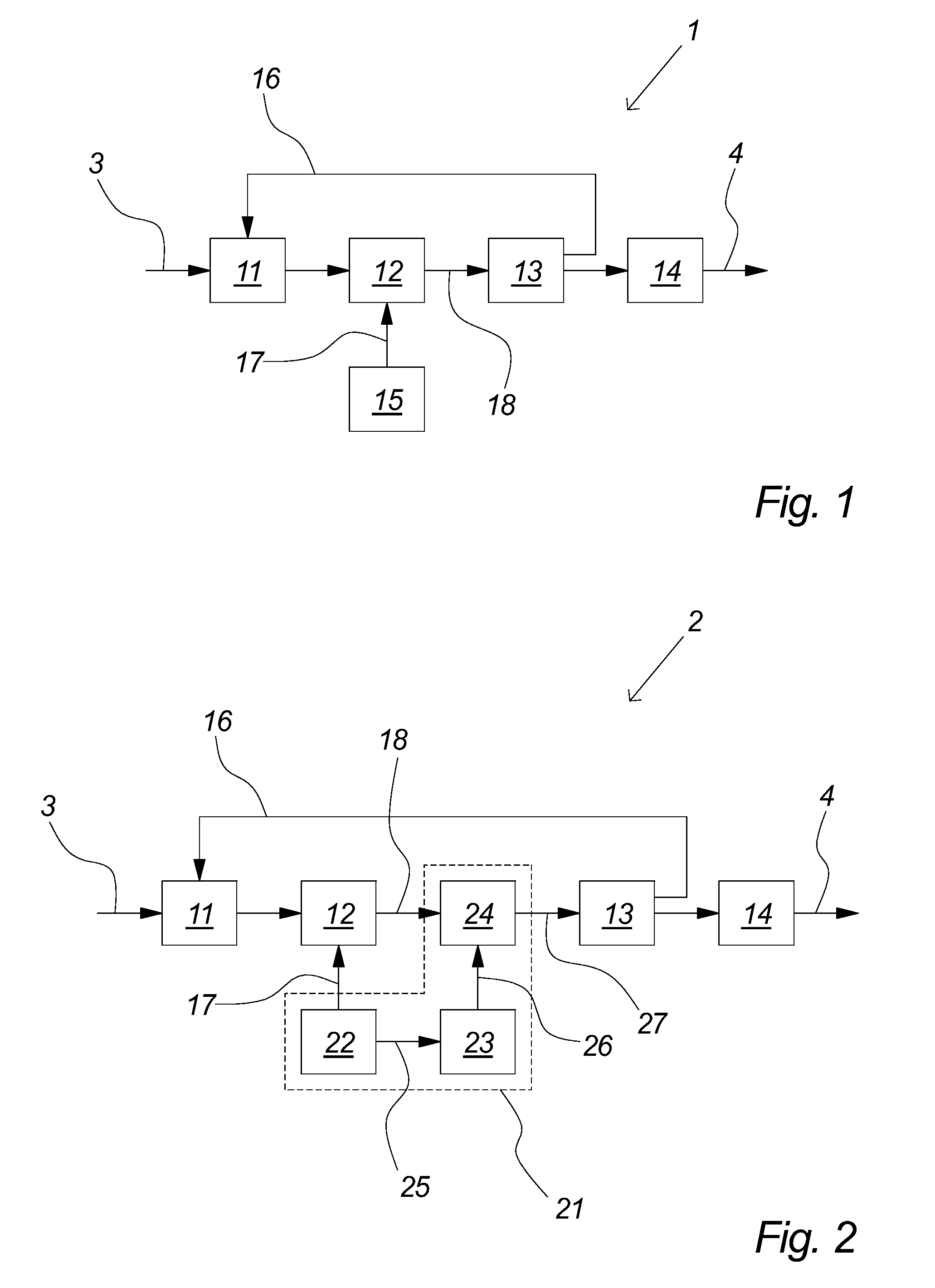
[0087]FIG. 1 illustrates a self-oscillating amplifier 1 wherein the problem of fluctuating switch frequency has been reduced by the known method of adding a small-signal periodic reference signal to the signal being amplified. It comprises a controller 11, comprising a suitable loop filter, preferably a linear low pass filter provided by an integrator, which provides suitable oscillation conditions in the loop. The controller 11 receives an input signal 3, e.g. an analog or digital audio signal, and its output is coupled to a modulator 12, comprising a suitable non-linear device, e.g. a comparator, which establishes a pulse width modulated (PWM) signal 18 from the output of the controller 11. The pulse width modulated signal 18 is amplified by a an output stage 13, comprising a suitable switching power stage, comprising suitable power switches, e.g. power FET's, controlled by the pulse width modulated signal 18. The output of the output stage 13 is preferably smoothed, i.e. decoded,...


PUM


Abstract

The present invention relates to a self-oscillating modulator (2) comprising a PWM cycle constrainer (21). The present invention further relates to a method of stabilising the switch frequency of a self-oscillating modulator operating on a high level input signal, whereby at least one PWM cycle constraint representative signal (26, 32, 33) is applied to a pulse width modulated signal (18) within said self-oscillating modulator (2). The present invention further relates to a method of avoiding pulses narrower than a predetermined minimum pulse width or wider than a predetermined maximum pulse width in a self-oscillating modulator (2) operating on a high level input signal, whereby at least one PWM cycle constraint representative signal (26, 32, 33) is applied to a pulse width modulated signal (18) within said self-oscillating modulator. The present invention further relates to a method of providing at least one PWM cycle constraint representative signal (26, 32, 33) for use in a self-oscillating modulator, whereby said PWM cycle constraint representative signal is established by the steps of: providing a periodic signal (17, 25, 31) by means of a reference signal generator (22), providing a square wave signal (31) on the basis of, and in synchrony with, said periodic signal (17, 25), and providing said PWM cycle constraint representative signal (26, 32, 33) on the basis of, and in synchrony with, said square wave signal (31).

Description

FIELD OF THE INVENTION[0001]The present invention relates to self-oscillating amplifiers or modulators.BACKGROUND OF THE INVENTION[0002]Self-oscillating pulse width modulation (PWM) amplifiers, e.g. for audio applications, are generally recognised as advantageous over common PWM amplifiers that modulates the input signal by means of a triangle or saw tooth reference signal, as they provide for a significant better error attenuation, e.g. easily more than 20 dB better error attenuation at 20 kHz.[0003]Known self-oscillating PWM amplifiers do, however, also suffer from a disadvantage, as their switch frequency fluctuates with the level of the input signal. The switch frequency decreases with increasing input level, and may typically be halved at input signals at 80% of maximum level. Among other things, this problem complicates operating more amplifiers simultaneously, e.g. in a multi-channel application, due to cross-talk, and moreover, it also increases problems with cross-talk to o...

Claims


Application Information

Patent Timeline
IPC IPC(8): H03K7/08
CPCH03M1/508
Inventor ARKNAES-PEDERSEN, LARSPEDERSEN, KIM RISHOJ
Owner TC-GROUP
Why Eureka
Try Eureka