
Reinforced reflective polarizer films

a reflective polarizer and film technology, applied in the field of optical films, can solve the problems of increasing the amount of polarized light incident on the lcd panel, presenting challenges in manual assembly and handling processes, and it is impractical to simply change the thickness of the reflective polarizer without changing its optical or cosmetic characteristics

Inactive Publication Date: 2007-07-05
3M INNOVATIVE PROPERTIES CO
View PDF82 Cites 87 Cited by
  • Summary
  • Abstract
  • Description
  • Claims
  • Application Information

AI Technical Summary

Benefits of technology

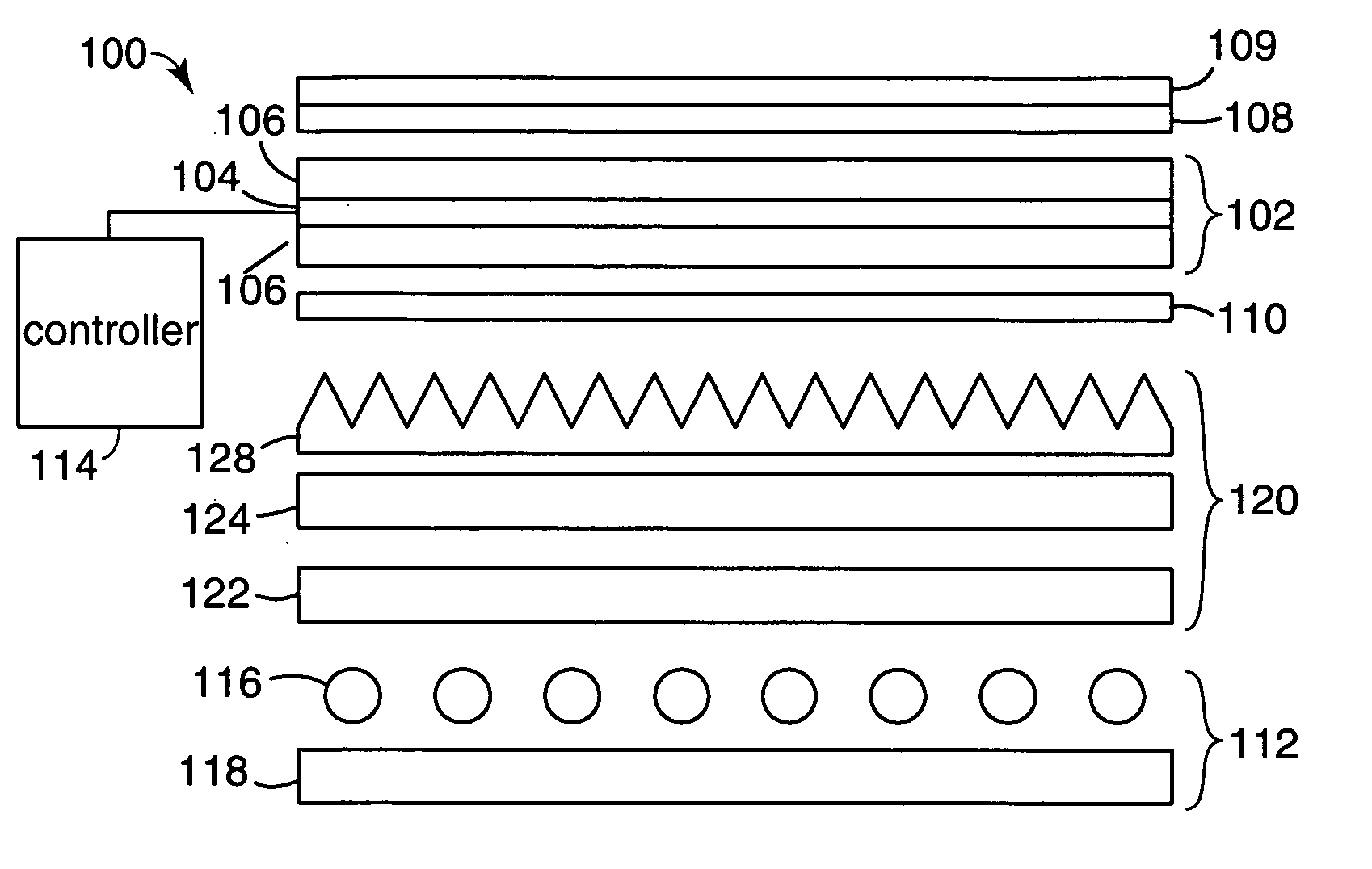
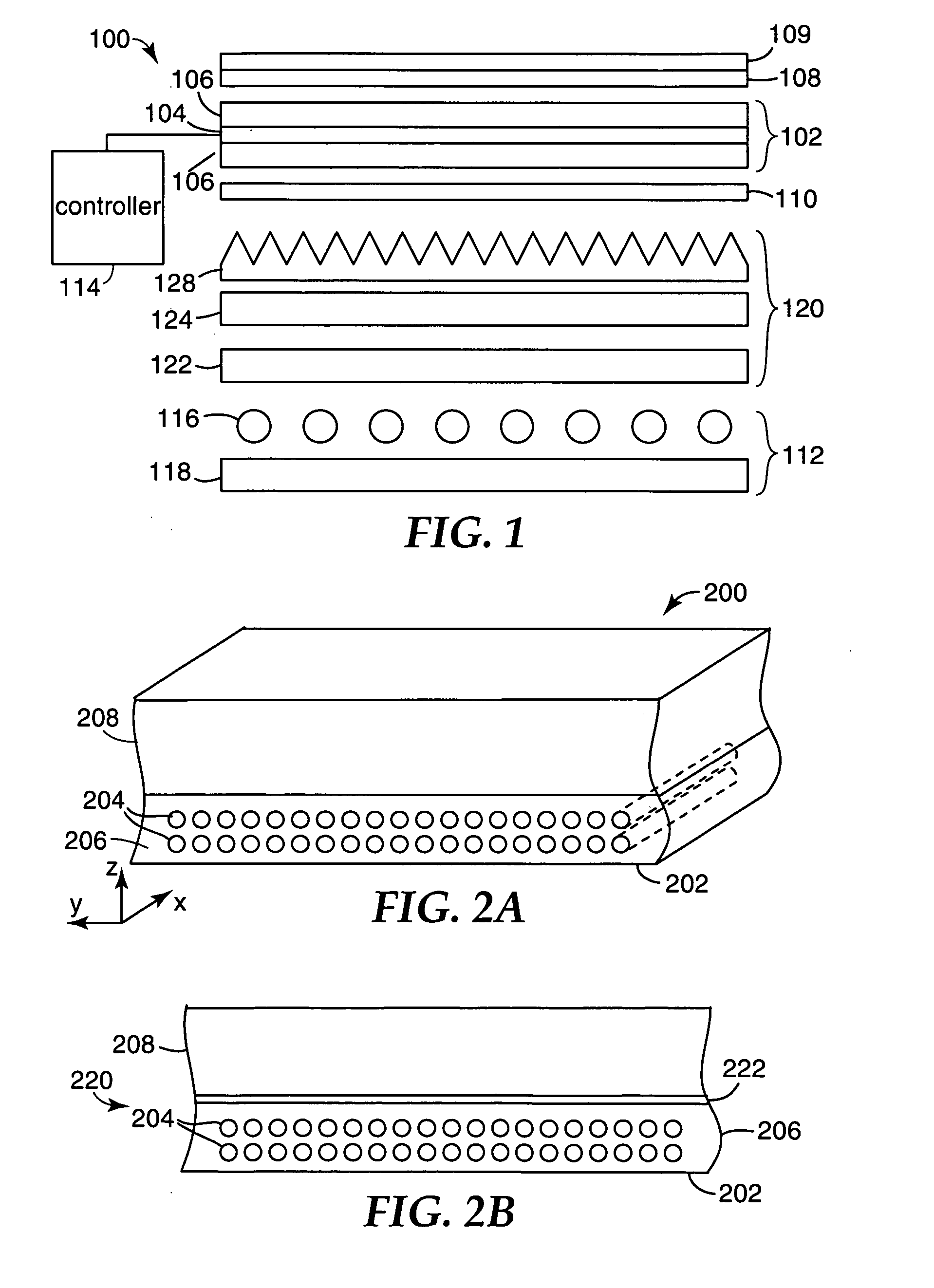
[0005] Another embodiment of the invention is directed to a display system that includes a display panel, a backlight and a reinforced reflective polarizer disposed between the display panel and the backlight. The reinforced reflective polarizer includes a first layer formed from a polymer matrix embedded with inorganic fibers. The reinforced reflective polarizer a

Problems solved by technology

This recycling process results in an increase in the amount of the polarized light that is incident on the LCD panel.
Such polarizing films are thin, typically a tens or a few hundreds of microns and, therefore, present challenges in manual assembly and handling processes, especially when used in larger display systems.
It is often impractical to simply change the thickness of the reflective polarizer without changing its optical or cosmetic characteristics.
The use of a thick substrate, however, increases the thickness of the display unit, and also leads to increases in the weight and, possibly, in the optical absorption.
The use of a thicker polymer substrate also increases thermal insulation, reducing the ability to transfer heat out of the display.
This leads to an increase in the distorting effects that are associated with higher heating, for example film warping.
Moreover, the lamination of the film to the thick polymer substrate makes the device thicker and heavier, without providing any improvement in the optical function of the display.

Method used


Image

  • Reinforced reflective polarizer films
  • Reinforced reflective polarizer films
  • Reinforced reflective polarizer films

Examples


example 1

DBEF Directly Attached to Composite Layer

[0125] In this example, a fiber reinforced layer was formed on a pre-existing layer of DBEF, a multilayer polymeric reflective polarizer manufactured by 3M Company. This polarizer is very similar to the commercially available polarizer sold by 3M Company as DBEF-P2, but has thinner skin layers. The fiber was fiber material A, listed in Table I. The resin mixture, Resin Mixture 1, was formed with the following weight % of the different resin components:

Resin ComponentWgt %C48.85D29.42E5.07F15.25G1.04

[0126] Resin Mixture 1 had a measured refractive index of 1.5470 or 1.5462, depending on the batch, after curing. In this example, four individual sheets of DBEF were primed and a layer of woven fiberglass and resin were applied to, degassed, and cured onto each side of each of the pieces of DBEF film. The primer was applied to improve the adhesion of the acrylate resin to the DBEF film. One primer is comprised of hexanediol diacrylate 97% (w / w...

example 2

DBEF Directly Attached to Composite Laver

[0134] Example 2 used fiber material A for reinforcement, but with a reactive silane-based CS767 finish on the glass fiber. This is a surface finish claimed by the manufacturer to improve adhesion of the glass fibers to epoxy, polyamide and cyanate ester resins. The resin mixture, Resin Mixture 3, was formed with the following weight % of the different resin components:

Resin ComponentWgt %C69.3H29.7G1.04

[0135] After curing, Resin Mixture 2 had a measured refractive index of 1.5517. A layer of woven fiber fabric glass and resin were applied to, degassed, and cured onto each side of a piece of primed DBEF film, as described above for Example 1.

[0136] A summary of the optical properties of the sample made in Example 2 are included in Table III, and the mechanical properties are summarized in Tables IV and V.

example 3

DRPF Directly Attached to Composite Laver

[0137] Example 3 was the same as Example 2 except that the reflective polarizer was a sheet of diffuse reflecting polarizer film, supplied by 3M Company, St. Paul, Minn., under the name DRPF. The optical properties of the Example 3 samples are summarized in Table III.


PUM


Abstract

A display system includes a display panel, a backlight and a reinforced reflective polarizer disposed between the display panel and the backlight. The reinforced reflective polarizer includes a first layer formed from a polymer matrix embedded with inorganic fibers. The reinforced reflective polarizer also includes a second layer attached to the first layer. The second layer comprises a reflective polarizing layer.

Description

FIELD OF THE INVENTION [0001] The invention relates to optical films and more particularly to reflective polarizer films that are reinforced using inorganic fibers. BACKGROUND [0002] Optical films, such as reflective polarizer films, are often used in displays, for example, for managing the propagation of light from a light source to a display panel. In particular, a reflective polarizer film is often used for transmitting, for the most part, one polarization of light that is incident on a liquid crystal display (LCD) panel, and for reflecting, for the most part, the light in the orthogonal polarization. The reflected light is recycled and returned to the reflective polarizer after at least some of the light has had its polarization altered to a state that is, for the most part, transmitted through the polarizer. This recycling process results in an increase in the amount of the polarized light that is incident on the LCD panel. [0003] As display systems increase in size, the area o...

Claims


Application Information

Patent Timeline
IPC IPC(8): G02F1/1335
CPCG02B5/02G02B5/045G02B5/3016G02B5/3025G02F2001/133607G02B5/3083G02F1/133536G02F1/133555G02B5/3041G02F1/133607
Inventor WRIGHT, ROBIN E.BENSON, OLESTER JR.HEBRINK, TIMOTHY J.OUDERKIRK, ANDREW J.FLEMING, PATRICK R.HART, SHANDON D.THUNHORST, KRISTIN L.
Owner 3M INNOVATIVE PROPERTIES CO
Learn More