Optical fingerprint imaging system and method with protective film

a fingerprint imaging and optical technology, applied in the field of electronic acquisition of fingerprints, can solve the problems of insufficient detail, inability to make a clear match, and inability to identify this unknown fingerprint,

Active Publication Date: 2007-07-05
CAREFUSION 303 INC
View PDF17 Cites 34 Cited by
  • Summary
  • Abstract
  • Description
  • Claims
  • Application Information

AI Technical Summary

Benefits of technology

[0014] Briefly and in general terms, the present invention is directed to a system and a method for an imaging system, protective film, and method for protecting a platen from degradation. In accordance with certain aspects of the invention, there is provided an optical fingerprint imaging system for acquiring fingerprint images, the imaging system comprising an optically transparent platen having an exterior surface through which a fingerprint image is to be acquired, a protective film comprising a material that is substantially free from imperfections that would affect transmission of light in acquiring a fingerprint image and which is substantially chemically in

Problems solved by technology

Without enough clarity, enough minutiae may not be obtained to make a clear match, if a match can be made at all.
If assembled successfully, the fingerprint image has been “acquired.” However, if a fingerprint image of low clarity and resolution is produced because of a cloudy, distorted, scratched, or imperfect platen, the number of minutiae regarding that fingerprint may be so limited that correlation of that minutiae with a data base of fingerprint images may result in no correlation with another fingerprint or may result in a correlation with a large number of fingerprints thus making it impossible to identify this unknown fingerprint.
Unclear fingerprint images in electronic acquisition systems may be caused by (1) lack of contrast between the ridges and valleys, (2) interference caused by latent fingerprints on the platen, (3) dirt on the platen resulting from use or environmental conditions, (4) scratches or other defects to the platen resulting from use, vandalism, or environmental conditions, (5) excessive pressure between the finger tip and the platen, (6) poor contact between the finger tip and platen resulting in a poor reflected image, (7) distortion caused by rolling the finger over the platen, (8) poor resolution of the optical equipment, and (9) gross distortion resulting from system configuration.
Other conditions may also result in an unclear image.
Whatever the cause, an unclear fingerprint cannot be as accurately read or compared with an existing fingerprint for verification or identification purposes.
What many prior fingerprint imaging devices have in common is a relatively costly platen that is integrated into the device.
However, some of the incident light may also be reflected at portions of the secon

Method used


Image

  • Optical fingerprint imaging system and method with protective film
  • Optical fingerprint imaging system and method with protective film
  • Optical fingerprint imaging system and method with protective film

Examples


Embodiment Construction

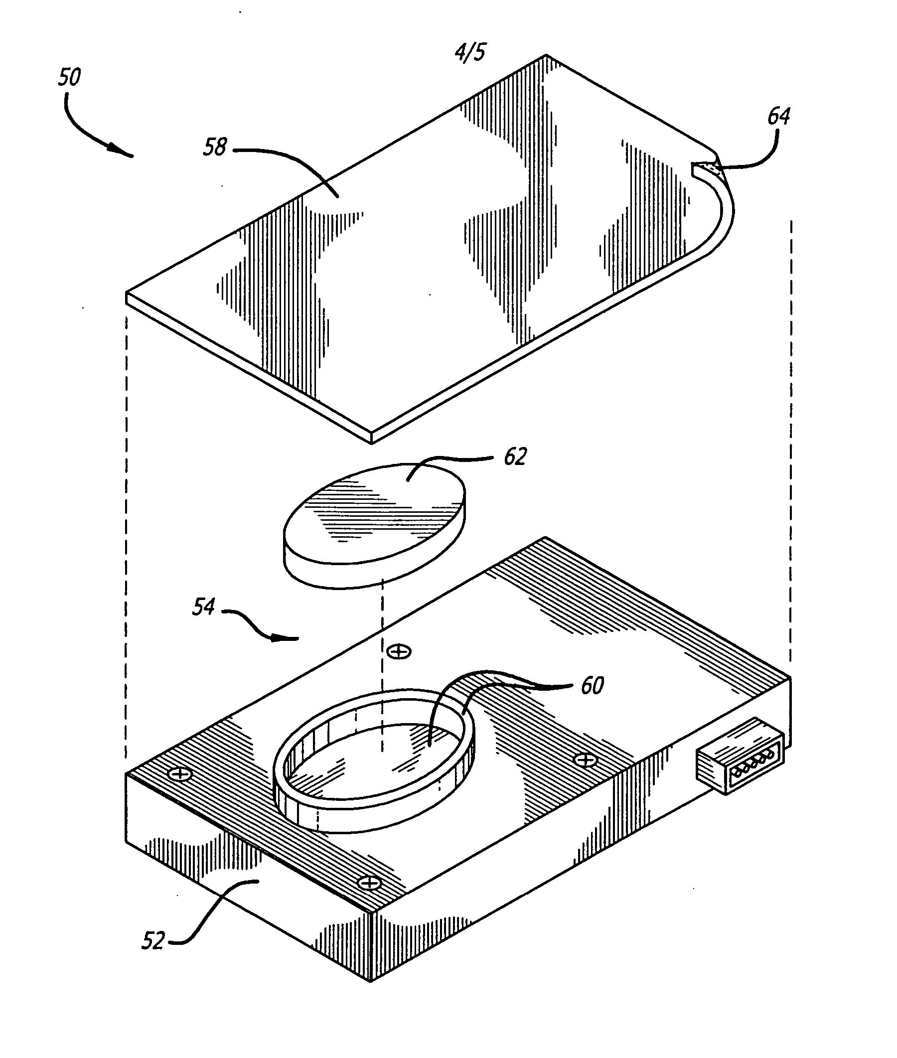
[0034] Referring now in more detail to the exemplary drawings, wherein like reference numerals designate corresponding or like elements among the several views, there is shown in FIG. 5 a perspective view of an optical fingerprint imaging device 50 and in FIG. 6 an exploded view of the imaging device. The device includes a housing 52 and a platen 54 disposed thereon. The platen is covered by a removable protective film 58. In this embodiment, the platen includes a first layer 60 and a second layer 62. The protective film 58 is removably attached to the second layer and to the housing. The platen is optically transparent in that it allows light from within the imaging device to readily travel through the platen to accurately produce a fingerprint image of a finger pressed onto the platen for verification or identification purposes.

[0035] With particular reference to FIG. 6, the first layer 60 of this embodiment is rigid and preferably, though not necessarily, planar. The first layer...


PUM


Abstract

An optical fingerprint imaging system comprises an optically transparent platen and a protective film removably attached to the platen with an adhesive. The protective film protects the platen from scratches, pits, and other surface damage and is substantially chemically inert to petroleum-based substances which may come into contact when receiving a finger pressed to take a fingerprint image. The adhesive has a selected cohesive strength that allows the protective film and adhesive to be removed from the platen without leaving behind an adhesive residue. The protective film can be replaced periodically as part of maintenance of the platen to allow continued acquisition of accurate fingerprint images. A method for protecting a platen is also disclosed.

Description

BACKGROUND [0001] The invention relates generally to electronic acquisition of fingerprints and, more particularly, to a system and a method of protecting a platen of an optical fingerprint imaging device. [0002] Electronic fingerprint acquisition systems have been introduced in recent times to eliminate the need for ink or a chemical reagent. In such systems, the subject's finger tip is pressed against or rolled over a planar or curved transparent platen in an optical system. Light is directed through the platen and is reflected from the finger tip into an optical path including mirrors or prisms, a lens, and an electronic image sensor such as a CCD imager of the type employed in video cameras. The image of the fingerprint may be digitized, analyzed, printed out, stored, transmitted, or compared with an existing fingerprint or fingerprints. [0003] Fingerprint identification is an exacting science that requires the comparison of the many minute and unique characteristics of each fin...

Claims


Application Information

Patent Timeline
IPC IPC(8): G06K9/74
CPCG06K9/00053G06V40/1329
Inventor HERNANDEZ, SERGIO
Owner CAREFUSION 303 INC
Why Eureka
Try Eureka