Luminescent diode, fabrication method thereof, and backlight assembly having the same

a technology of backlight assembly and diode, which is applied in the field ofluminescent diodes, can solve the problems of shortening the life of the lamp, affecting the brightness of the assembly, so as to prevent external defects and improve brightness uniformity

Inactive Publication Date: 2007-07-05
LG DISPLAY CO LTD
View PDF3 Cites 52 Cited by
  • Summary
  • Abstract
  • Description
  • Claims
  • Application Information

AI Technical Summary

Benefits of technology

[0026] An advantage of the present invention is to provide an LED that improves brightness uniformity by preventing external defects that cause brightness nonuniformity, a fabrication method thereof, and a backlight assembly having the same.
[0027] Another advantage of the present invention is to provide an LED with a plurality of optical fibers disposed therein such that the optical fibers change an optical path for light, a fabrication method thereof, and a backlight assembly having the same.
[0028] Additional features and advantages of the invention will be set forth in the description which follows, and in part will be apparent from the description, or may be learned by practice of the invention. The objectives and other advantages of the invention will be realized and attained by the structures and method particularly pointed out in the written description and claims hereof as well as the appended drawings.
[0029] To achieve these and other advantages and in accordance with the purpose of the present invention, as embodied and broadly described, a luminescent diode (LED) for a liquid crystal display (LCD) device includes an LED chip that emits light on a side .surface of the LCD device; and an optical guide element on the LED chip that enlarges a radiation angle of the light.
[0030] In another aspect of the present invention, a method of fabricating a luminescent diode (LED) includes mounting an LED chip on a substrate; electrically connecting the LED chip by wire bonding; forming a partition wall over edges of the substrate; molding a first insulating material into an interior surrounded by the partition wall; fixing an optical guide element in the first insulating material; and molding a second insulating material on the first insulating material.
[0031] In another aspect of the present invention, a backlight assembly includes a light source having an optical guide element, wherein the optical guide element enlarges a radiation angle of light; and an optical sheet that diffuses and condenses light emitted from the light source.

Problems solved by technology

A backlight assembly including a CCFL is problematic because mercury contained in the lamp bonds easily with metal to form an amalgam.
This shortens the lifetime of the lamp.
For example, as temperature varies, the brightness of the assembly may vary severely.
Also, it is problematic to dispose of mercury, a virulently poisonous heavy metal.
However, backlight assemblies including an LED do not have these shortcomings.
This causes the brightness of the LCD device to become non-uniform.
These non-uniformities cause hot spots.
Hot spots are external defects in LCD devices and therefore, result in reduced LCD device production yields.

Method used


Image

  • Luminescent diode, fabrication method thereof, and backlight assembly having the same
  • Luminescent diode, fabrication method thereof, and backlight assembly having the same
  • Luminescent diode, fabrication method thereof, and backlight assembly having the same

Examples


Embodiment Construction

[0043] Reference will now be made in detail to an, embodiment of the present invention, example of which is illustrated in the accompanying drawings. Wherever possible, the same reference numbers will be used throughout the drawings to refer to the same or like parts.

[0044] The present invention incorporates a plurality of optical fibers in a luminescent diode (LED) to enlarge the radiation angle of light. This enables an improved image quality because hot spots caused by brightness nonuniformity are prevented due to the enlarged radiation angle of light.

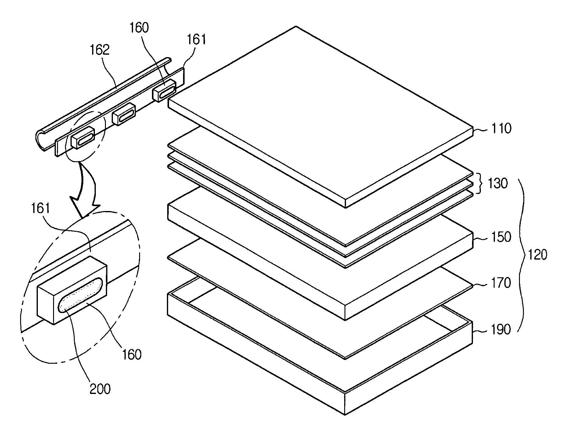
[0045]FIG. 4 is an exploded perspective view of an edge type liquid crystal display (LCD) device according to an embodiment of the present invention.

[0046] Referring to FIG. 4, the LCD device of the present invention includes a liquid crystal panel 110 that displays an image and a backlight assembly 120 that supplies light.

[0047] The backlight assembly 120 includes a bottom case 190. The backlight assembly 120 also includes a pl...


PUM


Abstract

A luminescent diode (LED) that improves brightness uniformity, a fabrication method thereof, and a backlight assembly having the same are disclosed. The LED includes an LED chip that emits light in a side surface of an LCD device; and an optical guide element on the LED chip that enlarges a radiation angle of the light. The LED may alternatively include an LED chip that emits light on a bottom surface of the LCD device; and an optical guide element on the LED chip that enlarges a radiation angle of the light. The radiation angle of light maximally enlarged to prevent hot spots caused by brightness nonuniformity. An enhanced image quality results.

Description

[0001] This application claims the benefit of Korean Patent Application No. 10-2005-0133193, filed on Dec. 29, 2005, which is hereby incorporated by reference for all purposes as if fully set forth herein. BACKROUND OF THE INVENTION [0002] 1. Field of the Invention [0003] The present invention relates to a luminescent diode (LED) that improves rightness uniformity. The present invention also relates to a fabrication method of the LED and a backlight assembly having the LED. [0004] 2. Discussion of the Related Art [0005] Data processors have been recently developed to have various shapes, various functions and higher data-processing speed. Because the data processed in the data processor is in the form of an electrical signal, a display device is needed to check the data processed in the data processor. [0006] Display devices include flat panel display devices. A liquid crystal display (LCD) device is a type of flat panel display device. An LCD device displays images using liquid cry...

Claims


Application Information

Patent Timeline
Patent Type & Authority Applications(United States)
IPC IPC(8): F21V7/04H01L33/00H01L33/56H01L33/58
CPCG02B6/0073G02B6/0085G02F1/133603H01L33/58G02F1/133615H01L33/56G02F1/133611H01L2224/48091H01L2224/49107H01L2924/181H01L2924/00012H01L2924/00014G02F1/1335
Inventor LEE, JAE YOUNG
Owner LG DISPLAY CO LTD
Why Eureka
Try Eureka