
Substrate bias voltage generator and method of generating substrate bias voltage

a voltage generator and substrate technology, applied in the field of voltage generators, can solve the problems of source, region and body, impurity concentration, and error in the sensing result of the sense amplifier, and achieve the effect of improving the refresh characteristic and the data storage capability of the cell

Inactive Publication Date: 2007-07-05
SK HYNIX INC
View PDF10 Cites 16 Cited by
  • Summary
  • Abstract
  • Description
  • Claims
  • Application Information

AI Technical Summary

Benefits of technology

[0014]Embodiments of the present invention provide a substrate bias voltage generator and a method of generating a substrate bias voltage, which can improve a refresh characteristic and a data storage capability of a cell by differently controlling a substrate bias voltage in a normal operation and a refresh voltage in a refresh operation.
[0015]Furthermore, embodiments of the present invention easily raise the substrate bias voltage, even when a capacitance value at a substrate bias voltage stage is large, by increasing the substrate bias voltage in a stepwise manner.

Problems solved by technology

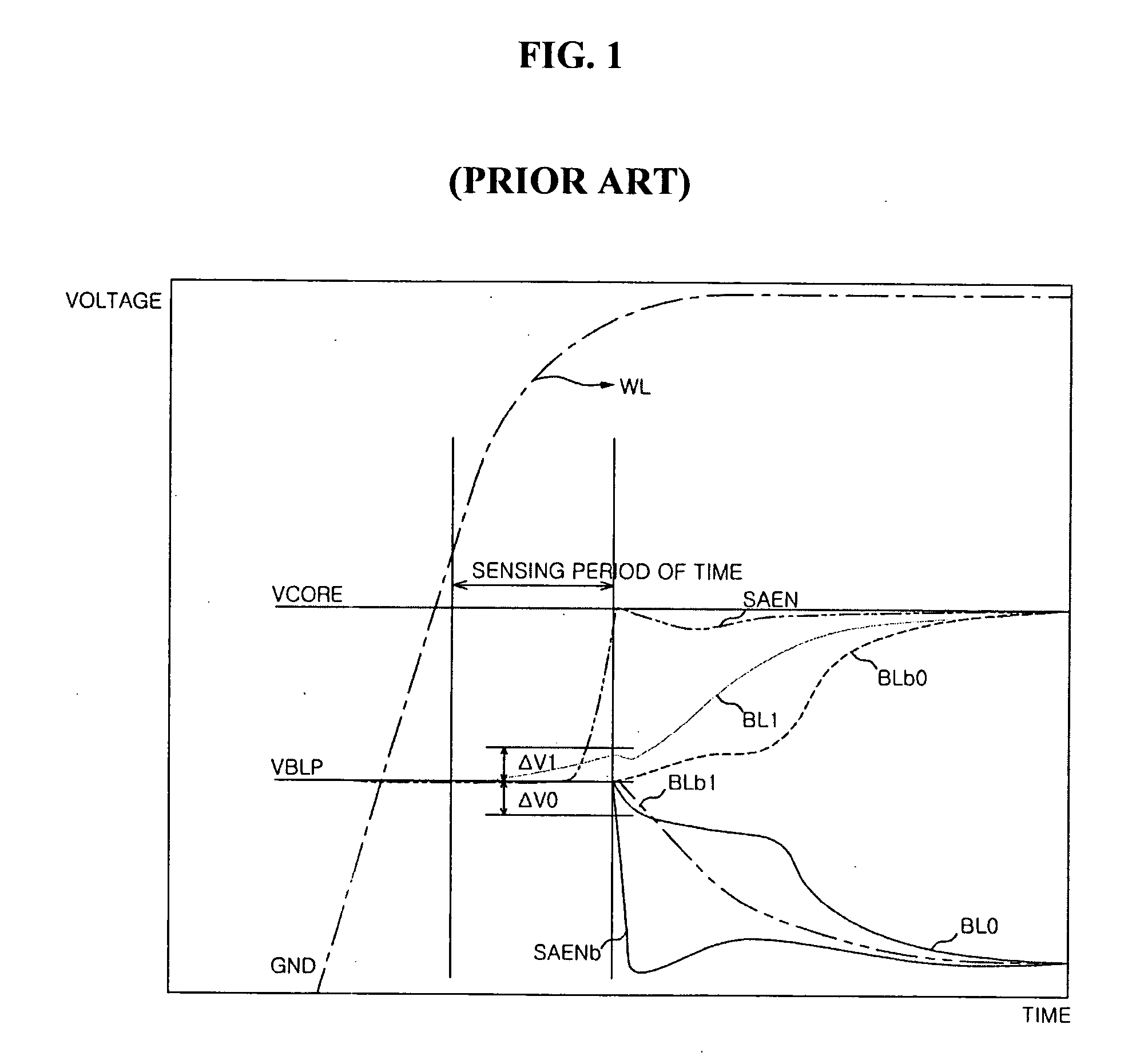
If the voltage difference between the bit line and the bit line bar is not sufficient, an error occurs in a sensing result of the sense amplifier.
When the shallow junction technique is applied, the impurity concentration in source / drain regions and the body increases, and as a result, the leaking between the source / drain regions and the body significantly increases.
Such a leaking phenomenon increases as a voltage applied to the body becomes smaller (that is, as a negative voltage becomes larger), which deteriorates the refresh characteristic.
Accordingly, in order to sufficiently store the cell data again through a refresh operation, a problem occurs in that a gate voltage should be sufficiently high.

Method used


Image

  • Substrate bias voltage generator and method of generating substrate bias voltage
  • Substrate bias voltage generator and method of generating substrate bias voltage
  • Substrate bias voltage generator and method of generating substrate bias voltage

Examples


Embodiment Construction

[0027]Hereinafter, preferred embodiments of the present invention are described in detail with reference to the accompanying drawings.

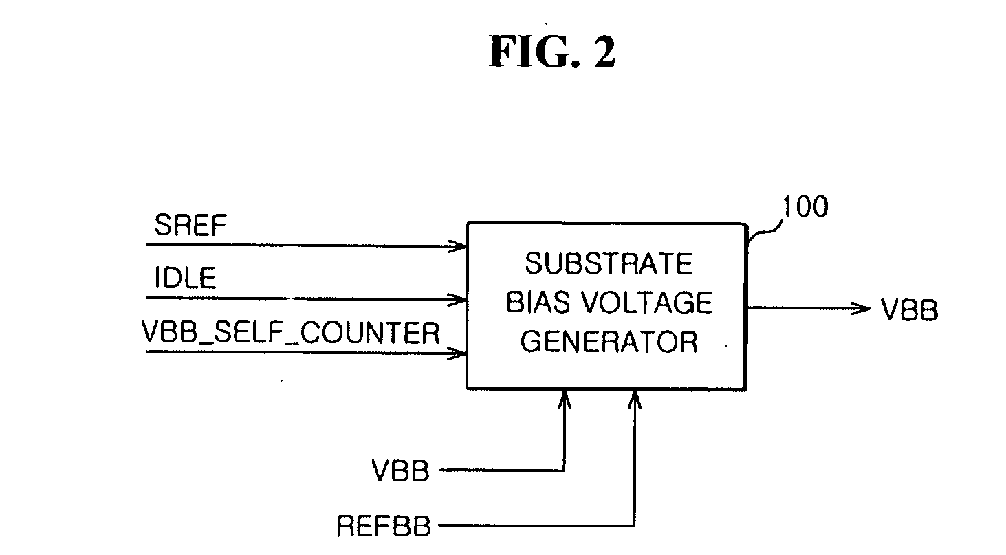
[0028]FIG. 2 is a view schematically illustrating a substrate bias voltage generator according to an embodiment of the present invention.

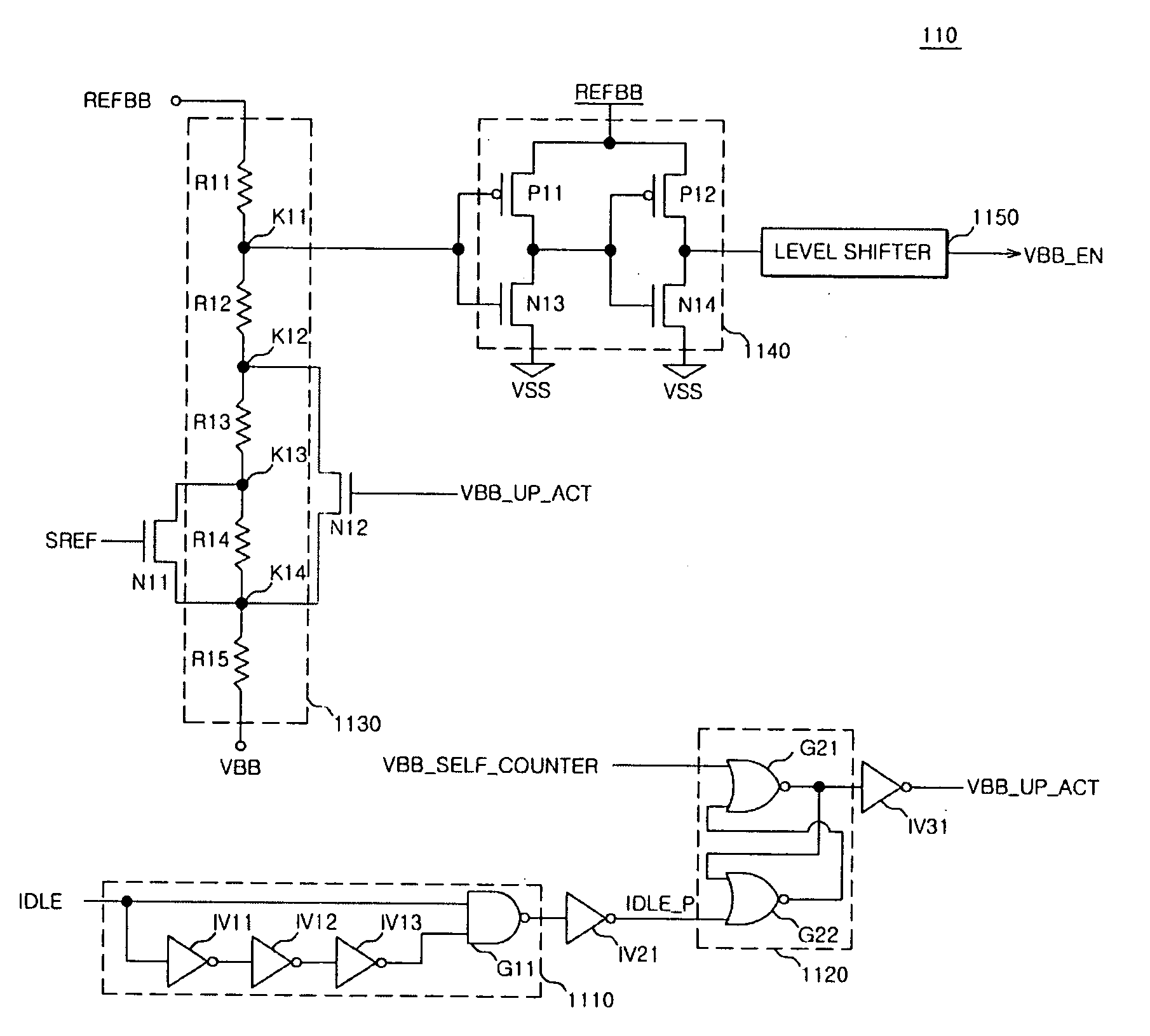
[0029]As shown in FIG. 2, a substrate bias voltage generator 100 according to an embodiment of the present invention compares a substrate bias voltage VBB with a reference voltage REFBB in response to a self-refresh signal SREF, an idle signal IDLE, and a refresh count, signal VBB_SELF_COUNTER, adjusts a pumping level with respect to the substrate bias voltage VBB, and then outputs the pumping-adjusted substrate bias voltage VBB.

[0030]The pumping level with respect to the substrate bias voltage VBB can be adjusted to be a first level VBB_NOR in a normal mode and to be a second level VBB_ST when the self-refresh signal SREF is enabled. Alternatively, the pumping level with respect to the substrate bias voltage VBB can...


PUM


Abstract

A substrate bias voltage detection unit compares a level of a substrate bias voltage with a reference voltage in response to a self-refresh signal, an idle signal, and a refresh count signal so as to output an oscillating driving signal, enables the oscillating driving signal when the substrate bias voltage is equal to or higher than a first level in a normal mode, disables the oscillating driving signal when the substrate bias voltage is at a second level in a self-refresh mode, and disables the oscillating driving signal when the substrate bias voltage is at a third level in the self-refresh mode. An oscillation unit outputs an oscillating signal according to the oscillating driving signal. A voltage pumping unit controls pumping of the substrate bias voltage according to an output signal of the oscillation unit and then outputs a pumped substrate bias voltage.

Description

BACKGROUND[0001]1. Technical Field[0002]The present invention relates to a voltage generator, and more particularly, to a substrate bias voltage generator and a method of generating a substrate bias voltage in which voltages having different levels can be supplied in normal and refresh operations in a semiconductor memory apparatus.[0003]2. Related Art[0004]In general, a sense amplifier of a semiconductor memory apparatus senses cell data when a voltage difference ΔV between an amount of electric charges, which are applied to a bit line according to an amount of electric charges stored in a cell, and an amount of electric charges, which are applied to a bit line bar by charge sharing, becomes sufficiently larger than an offset voltage of the sense amplifier. The voltage difference ΔV between the bit line and the bit line bar can be expressed by the following equation 1.ΔV=(VCORE−VBLP) / {1+(CB / CC)}  [Equation 1][0005]Here, the voltage VCORE is a sense amplifier driving voltage, and th...

Claims


Application Information

Patent Timeline
IPC IPC(8): G11C5/14
CPCG11C5/146G05F3/205G11C5/145G11C11/4074
Inventor LEE, JONG WON
Owner SK HYNIX INC
Learn More