Manufacturable vertical extended cavity surface emitting laser arrays

a laser array and vertical extension technology, applied in semiconductor lasers, instruments, optical elements, etc., can solve the problems of introducing artifacts, conventional dlp systems waste a considerable amount of light energy, and conventional dlp systems, so as to reduce the number of components that must be aligned during packaging

Active Publication Date: 2007-07-05
ARASOR ACQUISITION +1
View PDF1 Cites 113 Cited by
  • Summary
  • Abstract
  • Description
  • Claims
  • Application Information

AI Technical Summary

Benefits of technology

[0015] Arrays of vertical extended-cavity surface-emitting lasers (VECSELs) include a gain chip having an array of emitters, an end reflector, a nonlinear crystal for intra-cavity frequency conversion, a wavelength control element, and a polarization control element. The number of components that must be aligned during packaging is reduced by forming an optical unit that combines the functionality of at least two of the individual components of the VECSEL. The extended cavity has a forwards directed second harmonic beam directed away from the gain chip and a backwards directed second harmonic beam directed towards the gain chip. In one implementation, a dichroic beam splitter is included to selectively couple backwards directed light at the second harmonic frequency out of the cavity. In one implementation, the dichroic beam splitter includes at least one prism. In one embodiment the dichroic beam splitter redirects backwards-directed second harmonic beams to be extracted in a direction parallel to the forward directed second harmonic beams.

Problems solved by technology

There are several drawbacks to conventional DLP systems.
Additionally, conventional DLP systems waste a considerable amount of the light energy.
Second, some attributes of the displayed image, such as color saturation, are deleteriously affected by the color wheel, which can introduce artifacts into the displayed image.
Third, DLP systems include expensive optical elements.
However, conventional LED light sources tend to be more expensive than UHP lamps.
As a result, LEDs have many limitations as light sources in projection display systems
However, prior art semiconductor lasers have several drawbacks as light sources for display systems.
Compared with UHP white light sources, conventional semiconductor lasers are not cost-competitive and have a lower power (i.e., smaller total number of lumens of light).
Additionally, semiconductor lasers typically have unacceptable speckle characteristics due to the high coherence of semiconductor lasers.
In the context of a display system, a high degree of speckle results in light and dark patches across an image due to constructive and destructive interference from scatter centers.
In the prior art it was known that semiconductor lasers were not cost competitive with UHP lamps in many projection display applications.
However, in the prior art commercially available semiconductor lasers having the requisite luminance and satisfactory beam properties could not meet the total price point of $100 required for a RPTV system.
However, traditional approaches result in a complex system that is difficult to manufacture.
The optical elements must be initially aligned and kept in proper alignment, which increases the cost and complexity of manufacturing.
Generally speaking, the manufacturing cost of high power visible semiconductor lasers increases with each additional optical element added to the packaged optical device.
Moreover, each optical element that requires a critical alignment adds a significant cost to the final laser assembly.
However, in a projection display system a large number of Protera™ lasers at different wavelength would be required to have the range of wavelengths and total power required such that the total volume of the set of Protera™ laser would be immense compared to a conventional UHP lamp.
Another unresolved issue in the prior art is also how to best utilize semiconductor lasers as part of a total light engine solution.
Thus, a simplistic direct replacement of a UHP lamp with semiconductor lasers may not fully exploit the potential benefits of semiconductor lasers in a projection display system.

Method used


Image

  • Manufacturable vertical extended cavity surface emitting laser arrays
  • Manufacturable vertical extended cavity surface emitting laser arrays
  • Manufacturable vertical extended cavity surface emitting laser arrays

Examples


Embodiment Construction

I. Basic Architecture Of Extended Cavity Surface Emitting Light Source For Projection Displays

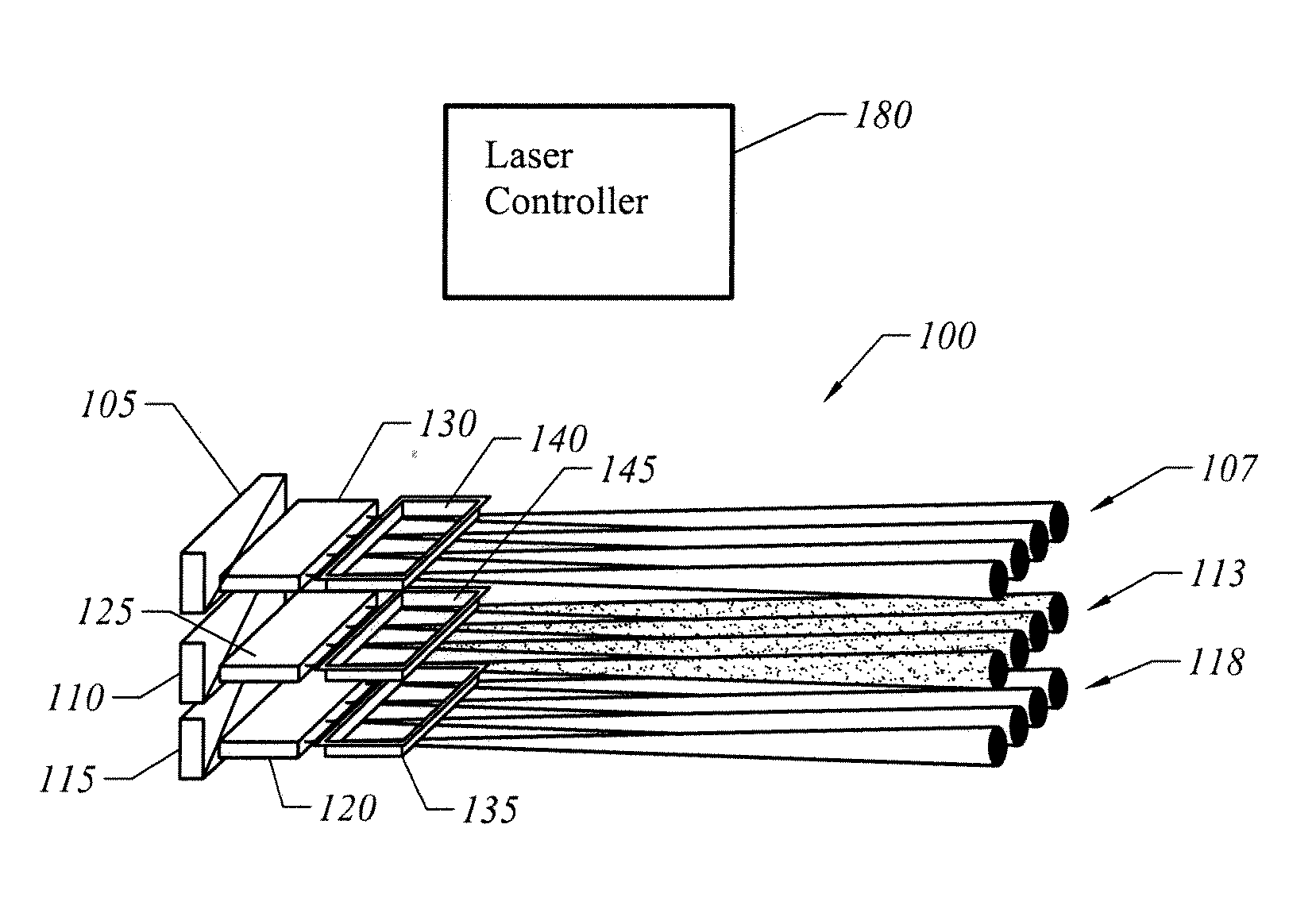
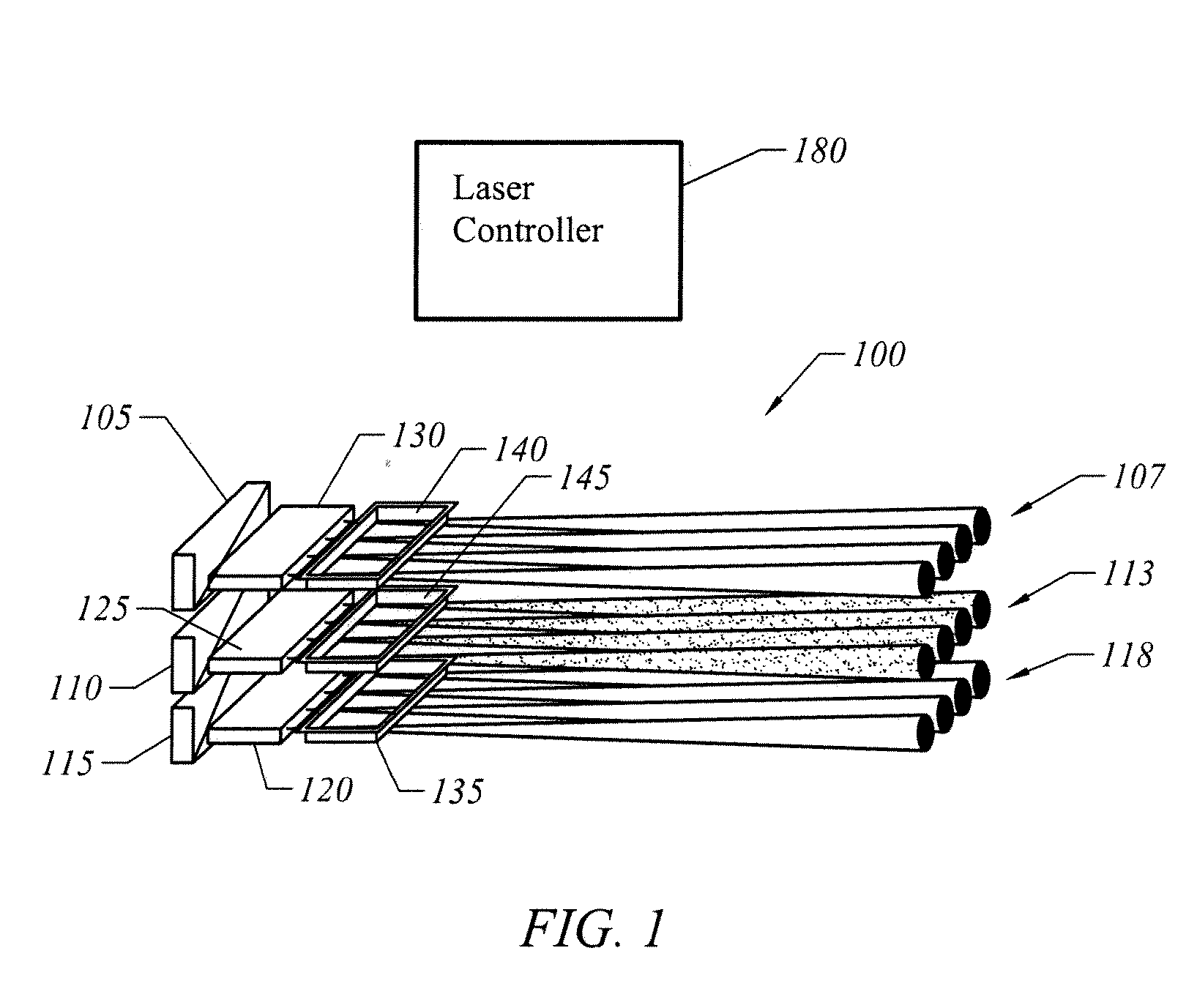
[0065]FIG. 1 is a profile view showing a light source 100 for generating light at several different colors required by a light processing (LP) system. In a red-green-blue (RGB) LP system the light source produces red, green, and blue light. A first array 105 of semiconductor lasers is used to generate a plurality of beams 107 of blue light from two or more individual lasers. A second array 110 of semiconductor lasers is used to generate a plurality of beams 113 of red light from two or more individual lasers. A third array of semiconductor lasers 115 is used to generate a plurality of beams 118 of green light from two or more individual lasers. Thus, light source 100 includes different sets of lasers. An individual set of two or more lasers generates a particular color of light used in the LP system. However, as described below in more detail, in a preferred embodiment individual lasers in ...


PUM


Abstract

Arrays of vertical extended cavity surface emitting lasers (VECSELs) are disclosed. The functionality of two or more conventional optical components are combined into an optical unit to reduce the number of components that must be aligned during packaging. A dichroic beamsplitter selectively couples frequency doubled light out of the cavity. In one implementation the dichroic beamsplitter includes at least one prism.

Description

CROSS-REFERENCE TO RELATED APPLICATIONS [0001] This application is a continuation-in-part of U.S. Pat. Ser. No. 11 / 396,341, filed on Mar. 30, 2006, which is a continuation in part of U.S. Pat. Ser. No. 11 / 193,317, “Projection Display Apparatus, System, and Method,” filed on Jul. 29, 2005 which claims the benefit and priority to provisional application Nos.: 60 / 592,890, filed on Jul. 30, 2004; 60 / 667,201 filed on Mar. 30, 2005; 60 / 667,202 filed on Mar. 30, 2005; 60 / 666,826 filed on Mar. 30, 2005; 60 / 646,072 filed on Jan. 21, 2005; and 60 / 689,582 filed on Jun. 10, 2005, the contents of each of which are also hereby incorporated by reference.FIELD OF THE INVENTION [0002] The present invention is generally related to light sources for use in display systems. More particularly, the present invention is directed to utilizing semiconductor lasers to replace conventional white light discharge lamps in projection display systems. BACKGROUND OF THE INVENTION [0003] Digital light processing (D...

Claims


Application Information

Patent Timeline
Patent Type & Authority Applications(United States)
IPC IPC(8): H01S5/00H01S3/10H01S3/08
CPCG02B27/102G03B21/2033G02B27/286G02B27/48H01S3/08072H01S3/1062H01S3/109H01S5/0071H01S5/0217H01S5/0224H01S5/02252H01S5/141H01S5/18305H01S5/18308H01S5/18358H01S5/18388H01S5/4093H01S5/423H04N9/3111H04N9/3114H04N9/3129H04N9/315H04N9/3197G02B27/141H01S5/02326H01S5/0234G03B21/00G03B21/14G03B21/26
Inventor SHCHEGROV, ANDREI V.WATSON, JASON P.LEE, DICKYUMBRASAS, ARVYDASDATO, RENEGREEN, JOHNJANSEN, MICHAELMOORADIAN, ARAM
Owner ARASOR ACQUISITION
Why Eureka
Try Eureka