Stent delivery system with improved delivery force distribution

a technology of delivery system and delivery force, applied in the field of stent delivery system, can solve the problems of limiting the reduction of the french size of the delivery catheter, the cost of the release wire delivery system is high, and the manufacturing process is more complicated

Inactive Publication Date: 2007-07-05
CORDIS CORP
View PDF67 Cites 99 Cited by
  • Summary
  • Abstract
  • Description
  • Claims
  • Application Information

AI Technical Summary

Benefits of technology

[0009] The invention comprises a stent or stent graft delivery system for use with one or more expandable stents or stent grafts. The one or more expandable stents or stent grafts may comprise a series of adjacent segments having voids therebetween such segments of a single stent or stent graft, or may comprise one or more adjacent stents or stent grafts having voids between such adjacent stents or stent grafts. In any case, the delivery system comprises a catheter having a lumen therethrough, an inner core over which the one or more stents or stent grafts is mounted for delivery from the catheter, and an outer sheath overlying the one or more stent or stent graft and the inner core. Whereas conventional stent delivery systems comprise an independent push rod that engages a proximal end

Problems solved by technology

Although the release wire tends to provide good placement of a stent or stent graft, such a release wire configuration increases the steps necessary for delivering a stent or stent graft to an intended treatment site and may

Method used


Image

  • Stent delivery system with improved delivery force distribution
  • Stent delivery system with improved delivery force distribution
  • Stent delivery system with improved delivery force distribution

Examples


Embodiment Construction

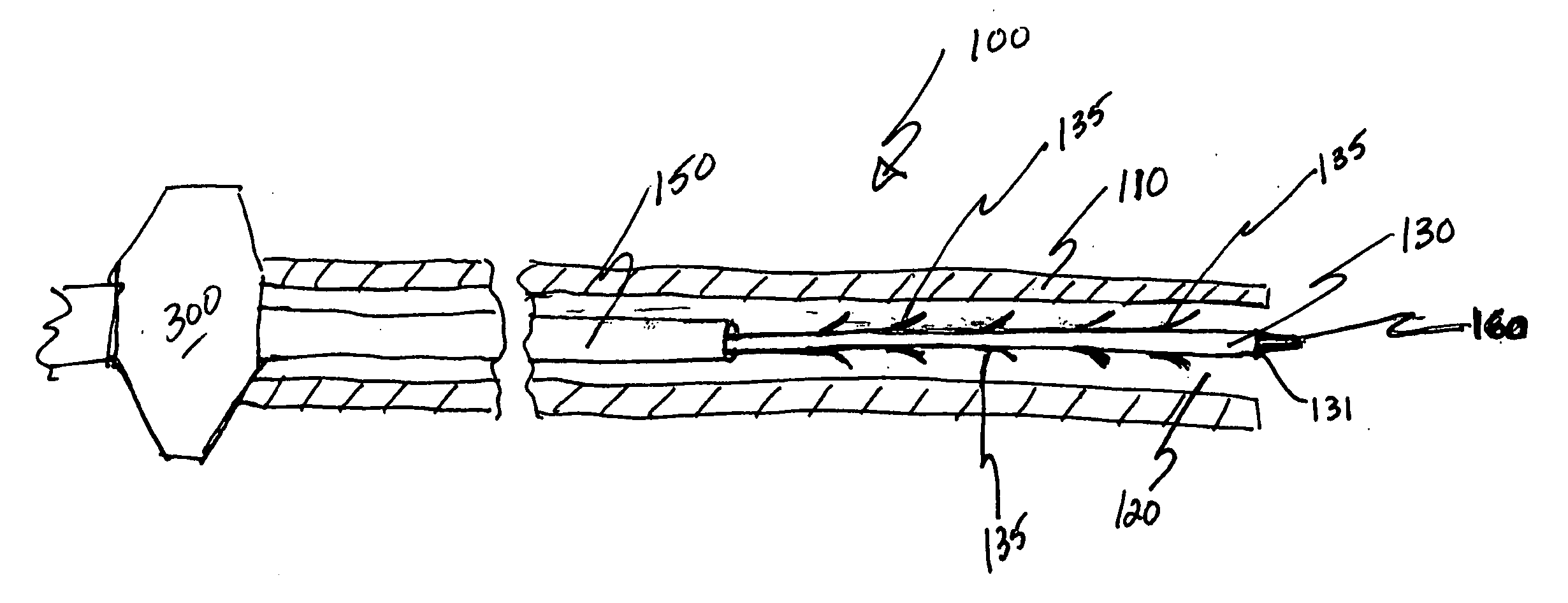
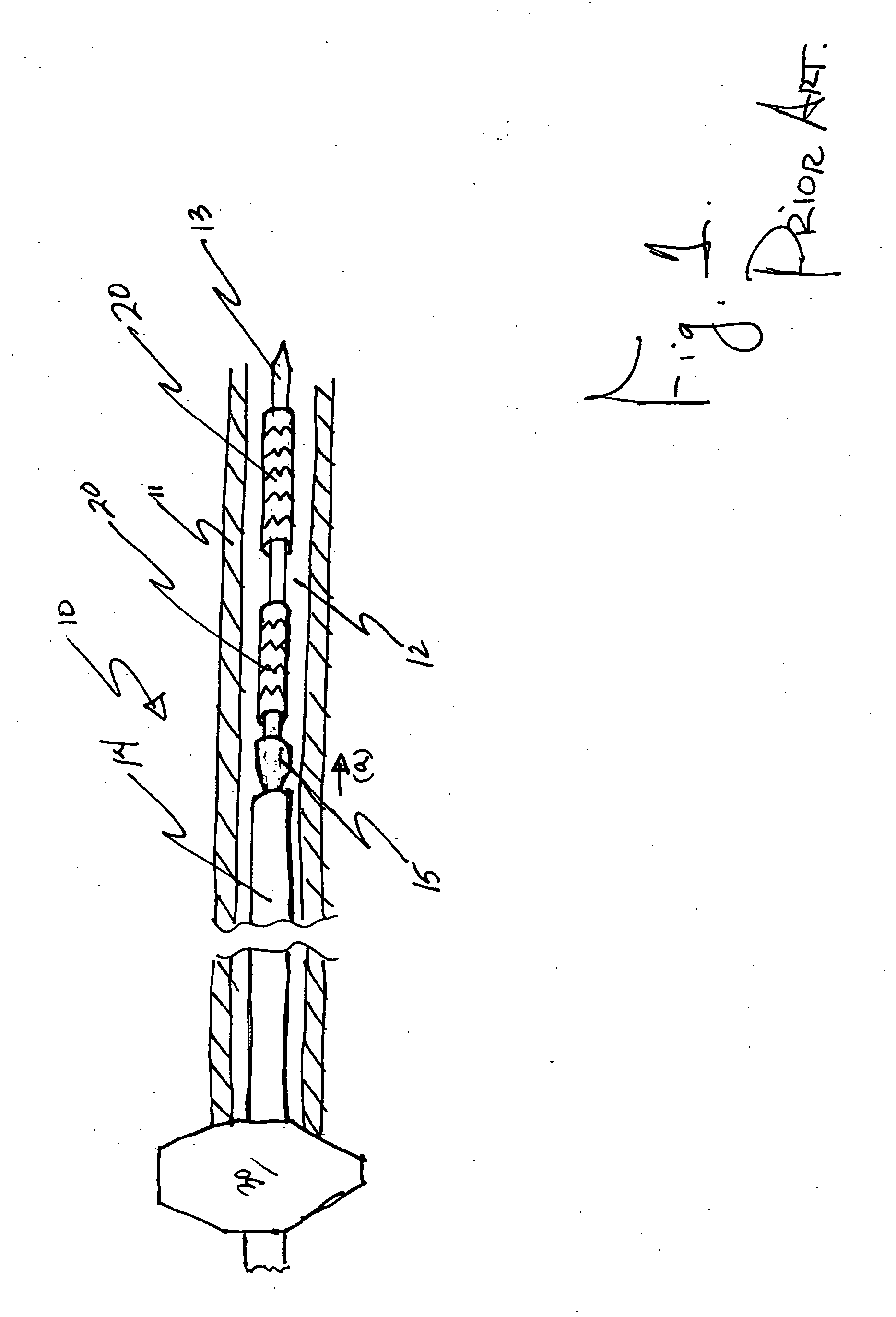
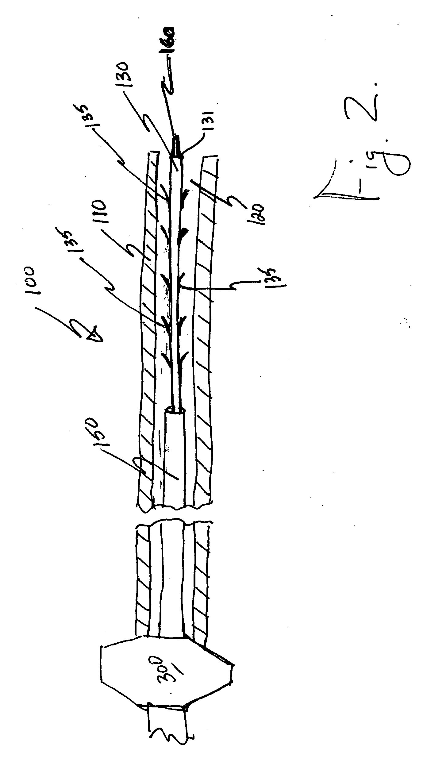
[0020]FIG. 1 illustrates a conventional catheter-based stent delivery system 10 having one or more stents 20 delivered therefrom to an intended treatment site. As shown in FIG. 1, the conventional stent delivery system 10 comprises a catheter 11 having a lumen 12 extending therethrough, an inner member 13, an outer sheath 14, and a pushrod 15. A hub 30 may be provided to help the operator handle insertion and withdrawal thereof. The pushrod 15 is moved in the direction of arrow (a) in order to maintain the one or more stents 20 in place as the outer sheath 14 is withdrawn to deploy the stents 20 as desired, or the pushrod is moved in the direction of arrow (a) in order to help push the one or more stents 20 into the desired deployed position. In either case, the use of the pushrod 14 against the proximal end of the one or more stents 20 tends to buckle the stents 20 or otherwise alter the spacing within or between the one or more stents 20. The altered spacing often results in an un...


PUM


Abstract

A stent delivery system that helps equalize delivery forces throughout a vascular prosthesis during delivery thereof to an intended treatment site. The delivery system comprises a catheter having a lumen therethrough, an inner core over which the one or more stents or stent grafts is mounted for delivery from the catheter, and an outer sheath overlying the one or more stent or stent graft and the inner core. The inner core of the further comprises a series of outwardly flared members that engage segments or fill voids in or between the stent, stents or stent grafts, respectively. The outwardly flared members of the inner core thus help maintain the segments of the stent or the one or more stents or stent grafts in spaced relation with respect to one another as delivery thereof occurs and as removal of the outer sheath occurs to position the one or more stents or stent grafts at the intended treatment site. The outwardly flared members thus help to distribute delivery forces more evenly throughout the one or more stents or stent grafts being delivered from the catheter. The outwardly flared members further aid accurate placement of the one or more stents or stent grafts by maintaining longitudinal spacing thereof during delivery.

Description

BACKGROUND OF THE INVENTION [0001] 1. Field of the Invention [0002] The invention generally relates to a stent delivery system. More specifically, the invention relates to a stent delivery system that improves emplacement of one or more stents or stent grafts by better distributing delivery forces during delivery thereof to an intended treatment site. [0003] 2. Related Art [0004] Balloon expandable stents and self-expanding stents are generally delivered in a cylindrical form, compressed to a smaller diameter, and placed within a vessel using a catheter-based delivery system. A femoral artery in the groin is typically accessed to deliver the stent graft to its intended position in the abdominal region, for example, the abdominal aortic artery. A guidewire is threaded from the femoral artery access and through the blood vessel to a point beyond the diseased part of the artery. [0005] The delivery system, carrying the stent or stent graft within it, is manipulated through the blood ve...

Claims


Application Information

Patent Timeline
IPC IPC(8): A61F2/06A61F2/82
CPCA61F2/95A61F2002/9665A61F2002/826
Inventor VAUGHAN, DENNIS
Owner CORDIS CORP
Why Eureka
Try Eureka