Telescopic shaft for vehicle steering

a technology of vehicle steering and telescopic shaft, which is applied in the direction of mechanical equipment, transportation and packaging, couplings, etc., can solve the problems of increasing processing costs, increasing sliding friction, and increasing so as to prevent the backlash in the rotational direction, high rigidity, and prevent the effect of excessive load

Inactive Publication Date: 2007-07-12
NSK LTD
View PDF77 Cites 31 Cited by
  • Summary
  • Abstract
  • Description
  • Claims
  • Application Information

AI Technical Summary

Benefits of technology

[0008] The present invention is made in view of aforementioned problems and has an object to provide a telescopic shaft for vehicle steering capable of realizing a stable sliding load, securely preventing backlash in the rotational direction, and transmitting torque under high rigidity.
[0022] As described above, according to the present invention, when a gap in the torque transmitting portions is converted into a rotation angle A and a possible flexural amount of the elastic member in the preload portion is converted into a rotation angle B, the rotation angle A is set to be less than the rotation angle B upon transmitting no torque. Accordingly, when high torque is transmitted, the torque transmitting portions transmitting primary torque can come into contact with each other securely earlier than the preload portion transmitting lower torque to remove backlash. As a result, it becomes possible to prevent an excessive load from applying on the preload portion, so that backlash in the rotational direction can be prevented and torque can be transmitted with high rigidity over an extended time period.

Problems solved by technology

However, in the former case, it is necessary to suppress backlash of the telescopic shaft to be minimum with suppressing the sliding load to be minimum, so that in the final cutting process, a die corresponding to a female shaft has to be selected among dies each having different over-pin diameter with an interval of few micrometers resulting in increase in processing cost.
In addition, backlash in the rotational direction becomes large as progress in wearing the nylon layer according to the used time length.
Moreover, with exposing to high temperature of the engine room, the nylon layer makes alteration in volume resulting in extreme increase in sliding friction and drastic acceleration of wear, so that backlash in the rotational direction becomes large.
Accordingly, since sufficient number of balls have to be disposed structurally to endure an input torque, there are structural defects such that it becomes difficult to be made compact as a telescopic shaft for vehicle steering, and it also becomes difficult to secure a sufficient collapse stroke upon collision.

Method used


Image

  • Telescopic shaft for vehicle steering
  • Telescopic shaft for vehicle steering
  • Telescopic shaft for vehicle steering

Examples


first embodiment

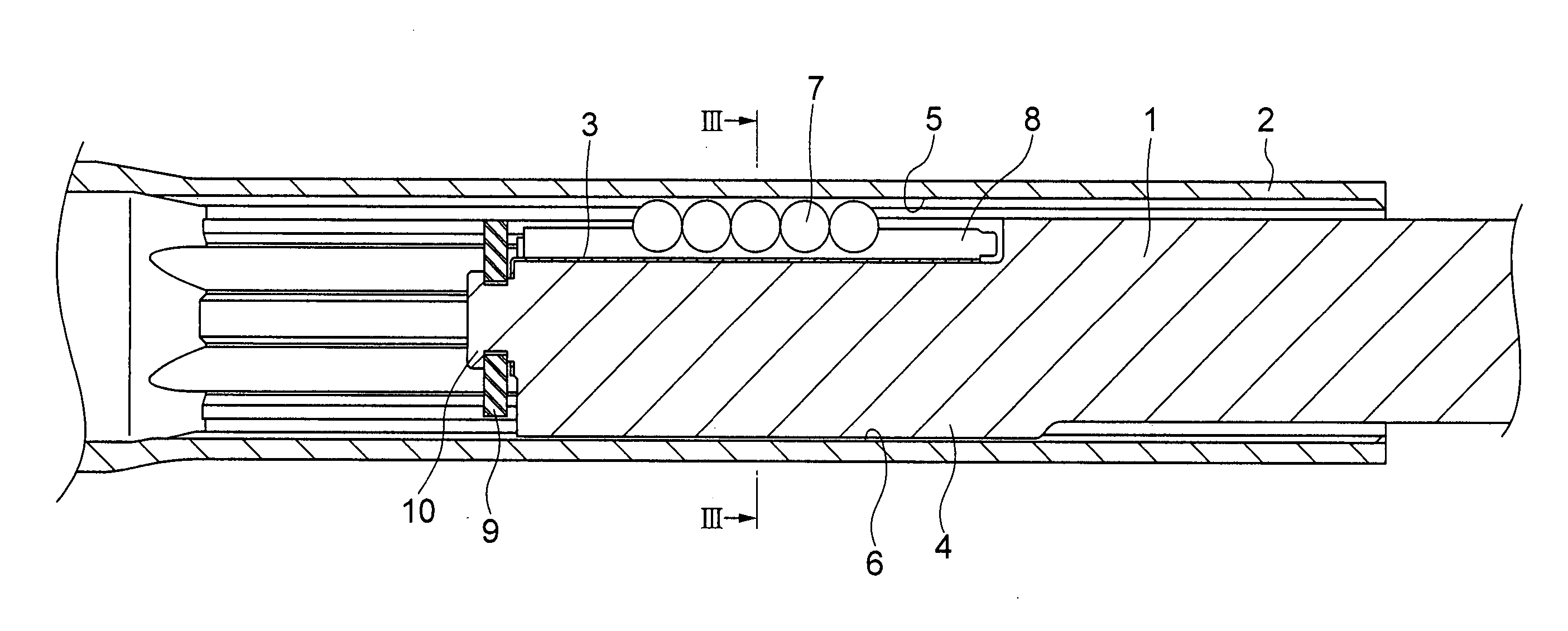
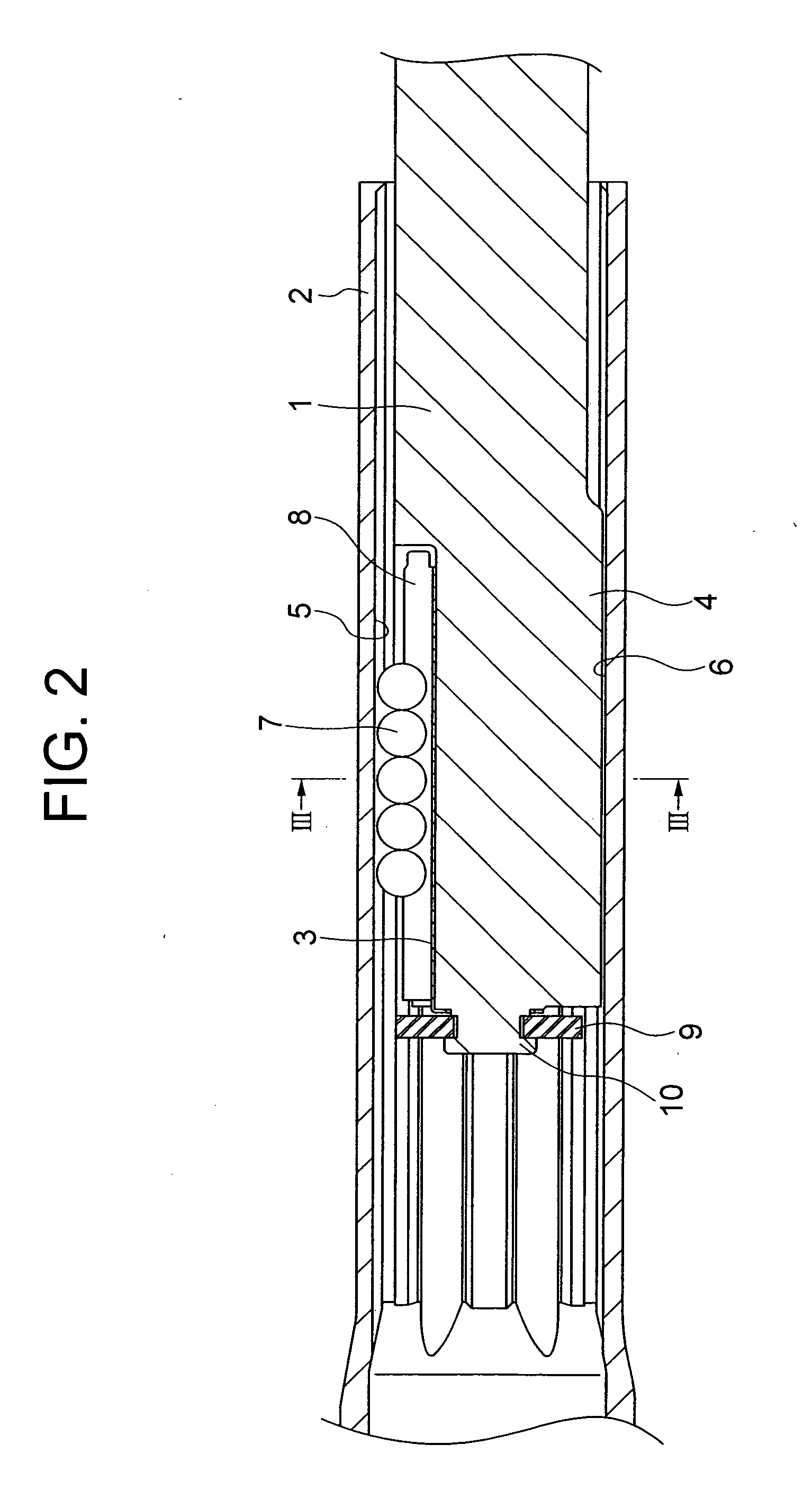
[0039]FIG. 2 is a vertical cross-sectional view showing a telescopic shaft for vehicle steering according to a first embodiment of the present invention.

[0040]FIG. 3 is a partial sectional view along a III-III line in FIG. 2.

[0041]FIG. 4 is a graph showing a relation between torque and a rotation angle of the telescopic shaft for vehicle steering according to the first embodiment of the present invention.

[0042] As shown in FIGS. 2 and 3, a telescopic shaft for vehicle steering (hereinafter called a telescopic shaft) is composed of a male shaft 1 and a female shaft 2 disposed concentrically around the center 0 and fitted unrotatably but slidably with each other.

[0043] In the first embodiment, although only a portion is shown in FIG. 3, a plurality of elongated projections 4 extending in the axial direction are formed on the outer surface of the male shaft 1. Although each of the axially elongated projections 4 is a male portion of a spline fitting, it may be a male portion of a s...

second embodiment

Variations in Second Embodiment

[0100]FIG. 10 is a cross-sectional view showing a telescopic shaft for vehicle steering according to a first variation of the second embodiment of the present invention.

[0101]FIG. 11 is a cross-sectional view showing a telescopic shaft for vehicle steering according to a second variation of the second embodiment of the present invention.

[0102]FIG. 12A is a vertical cross-sectional view showing a telescopic shaft for vehicle steering according to a third variation of the second embodiment of the present invention. FIG. 12B is a cross-sectional view along a b-b line in FIG. 12A.

[0103] In all of the following variations, each of the similar constructions to the first or second embodiment is attached to the same reference number, and the explanation thereof is omitted.

[0104] The first variation shown in FIG. 10 has a characteristic feature of forming a solid lubricant film 11 on the outer surface of the male shaft 1 relative to the second embodiment. I...


PUM


Abstract

A telescopic shaft for vehicle steering that is assembled into a steering shaft for a vehicle and has a female shaft and a male shaft that are fitted relatively unrotatably but slidably, the telescopic shaft for vehicle steering includes torque transmitting portions that are respectively disposed on an outer surface of the male shaft and on an inner surface of the female shaft and come in contact with each other for transmitting torque upon rotation, and a preload portion composed of a rolling member that is disposed between the outer surface of the male shaft and the inner surface of the female shaft at a different position from a position where the torque transmitting portions are located and rolls when the male shaft and the female shaft relatively move in the axial direction and an elastic member that is disposed adjacent to the rolling member in the diametral direction and gives pressure upon the male shaft and the female shaft through the rolling member, wherein when a gap in the torque transmitting portions is converted into a rotation angle A and a possible flexural amount of the elastic member in the preload portion is converted into a rotation angle B, the rotation angle A should be less than the rotation angle B upon transmitting no torque.

Description

TECHNICAL FIELD [0001] The present invention relates to a telescopic shaft for vehicle steering. BACKGROUND ART [0002] In a steering mechanism for a vehicle, in order to absorb axial displacement occurred upon traveling and to prevent the displacement and vibrations from being transferred onto a steering wheel, a telescopic shaft constructed by a male shaft and a female shaft that are spline-fitted to each other has been used in a portion of a steering mechanism. The telescopic shaft is required to be able to reduce backlash noises from the spline portion, backlash on the steering wheel, and sliding friction upon sliding in the axial direction. [0003] In order to fill the requirements, the spline portion of a male shaft of a telescopic shaft is coated with nylon and a sliding portion thereof is applied by grease, thereby absorbing and reducing metallic noises, metallic knocking noises, and the like, as well as reducing sliding friction and backlash in the rotational direction. In th...

Claims


Application Information

Patent Timeline
Patent Type & Authority Applications(United States)
IPC IPC(8): B62D1/18B62D1/185B62D1/19F16C3/035F16C25/08F16C33/58
CPCB62D1/185B62D1/192F16C33/58F16C29/12F16C3/035F16C29/123F16C29/007F16C2326/24F16D3/065F16D2300/22
Inventor YAMADA, TAKATSUGU
Owner NSK LTD
Why Eureka
Try Eureka