Multi-layer web formation section

a web and multi-layer technology, applied in papermaking, non-fibrous pulp addition, coatings, etc., can solve the problems of not producing a final product of optimum quality, unpredictability, and poor retention, and achieve effective dewatering, prevent damage to the web, and improve the effect of web formation

Inactive Publication Date: 2007-07-12
VALMET TECH INC
View PDF5 Cites 6 Cited by
  • Summary
  • Abstract
  • Description
  • Claims
  • Application Information

AI Technical Summary

Benefits of technology

[0025] No under-pressure peak occurs on the output side of the non-pulsating dewatering zone, because the structure is fixed. In this way that tendency damaging the web is avoided, which relates to the non-pulsating dewatering zone formed by a roll.
[0026] In the non-pulsating dewatering zone water can be removed even from a very wet web without breaking the structure of the web. In consequence of this, the web may be brought very wet to the formation shoe, where water is removed from the web through the openings of the non-pulsating formation shoe under the effect of under-pressure existing in the openings. A very effective dewatering is provided in this manner. After the non-pulsating dewatering zone the web is guided into the pulsating dewatering zone with such a dry-matter content that formation of the web can be improved by pulsating dewatering. The higher dewatering capacity also allows a higher production rate.
[0027] The capital and maintenance costs of a non-pulsating fixed formation shoe are lower than those of a roll and standby roll.
[0028] According to each purpose of use, the radius of the non-pulsating fixed formation shoe and the shoe length in the machine direction can be changed within a larger range than would be practical when using a roll. The fixed formation shoe may also be formed by several curves, for example, in such a way that the radius of the formation shoe is longer at the input end, but it becomes progressively shorter as a spiral-like arch towards the output end. In such a case the dewatering pressure is no longer constant over the formation shoe, but it remains non-pulsating nevertheless. The possibility of changing the radius in both the manners told above as well as the shoe length means that non-pulsating dewatering can always be designed to be suitable according to each application in a considerably easier way than is possible to do in connection with a roll.
[0029] The combination of a non-pulsating dewatering zone and a pulsating dewatering zone allows easier control of the dewatering between the non-pulsating and the pulsating dewatering zones, whereby the dewatering can be controlled more easily and better than in the known formers. In consequence of this, the balance between formation and retention can be better controlled and the strength properties of the web can be optimized. By adjusting the under-pressure level of the non-pulsating formation shoe it is possible to adjust the distribution of dewatering between the top and bottom surfaces of the web, which for its part affects the distribution of fines between the top and bottom surfaces. Hereby the fines content can be controlled in that surface of the pulp, which is combined with the partial web formed in the preceding wire unit. There must be sufficiently fines in the joining surfaces of the partial webs, so that a strong bond is formed between the partial webs.
[0030] The high dewatering capacity of the non-pulsating formation shoe at the beginning of the two-wire stretch makes it possible for the lip jet of the headbox to be very thick. The formation section can hereby be used within a large basis weight range. In addition, it is possible in the fixed formation shoe to use a long radius of curvature, whereby the tension of the outer wire travelling on the shoe causes less dewatering pressure on the pulp located in between the wires. This again reduces the flow tendency in the cross direction, which acts on the pulp travelling in between the wires, whereby fiber orientation errors are avoided in the pulp layers located in the edge areas of the wires.

Problems solved by technology

Making a web is still an art in part and science in part in that simply removing water as quickly as possible will not produce a final product of optimum quality.
When it is desirable to maintain or improve the quality of the final product when proceeding to higher production speeds, unforeseeable problems often occur, in consequence of which either the production quantity must be reduced to maintain the desired quality or the desired quantity must be given up in order to achieve a higher production quantity.
An undesirable distribution of fines and fillers may occur in the surface or internal parts of the final product, whereby retention will suffer.
A drawback of the roll jaw former is that the rotation of the formation roll brings about an under-pressure pulse on the discharge side of the roll nip.
Hereby the damaged web can no longer withstand powerful pulsating, whereby the dewatering must be limited in the pulsating dewatering zone.
The price of the formation roll and its spare parts as well as the need for roll service and the resulting time of machine standstill also constitute a disadvantage.
In addition, it has been found to be a problem with the roll jaw former that the dewatering capacity is not sufficient at high velocities and with dense pulps.
In addition, the big rotating roll forms a source of vibrations in the formation section.
In practice, the radius of the formation roll cannot be very long, whereby the wires travelling over it are subjected to a great force directed towards the shell.
The big formation roll also takes much space and, in addition, a standby roll is also needed at all times.
However, the list jaw former is sensitive to many errors, such as changes occurring in the pulp jet, and this circumstance restricts the former's efficient operation.
The dewatering is quite asymmetric to begin with, which in the Z direction results in unequal sidedness in the web structure, especially as regards the distribution of fillers and the anisotropy of fiber orientation.
Since the dewatering of pulp is done under a pulsating pressure to begin with, retention is low.
With such an arrangement a good retention and a symmetric paper have been achieved, but poorer formation results than with the traditional list jaw formers.
This is due to the fact that the rotational motion of the formation roll brings about an under-pressure peak in the web after the formation roll, which will damage the web already formed.
A big formation roll also takes much space and, in addition, a standby roll is also required at all times.

Method used


Image

  • Multi-layer web formation section
  • Multi-layer web formation section
  • Multi-layer web formation section

Examples


Embodiment Construction

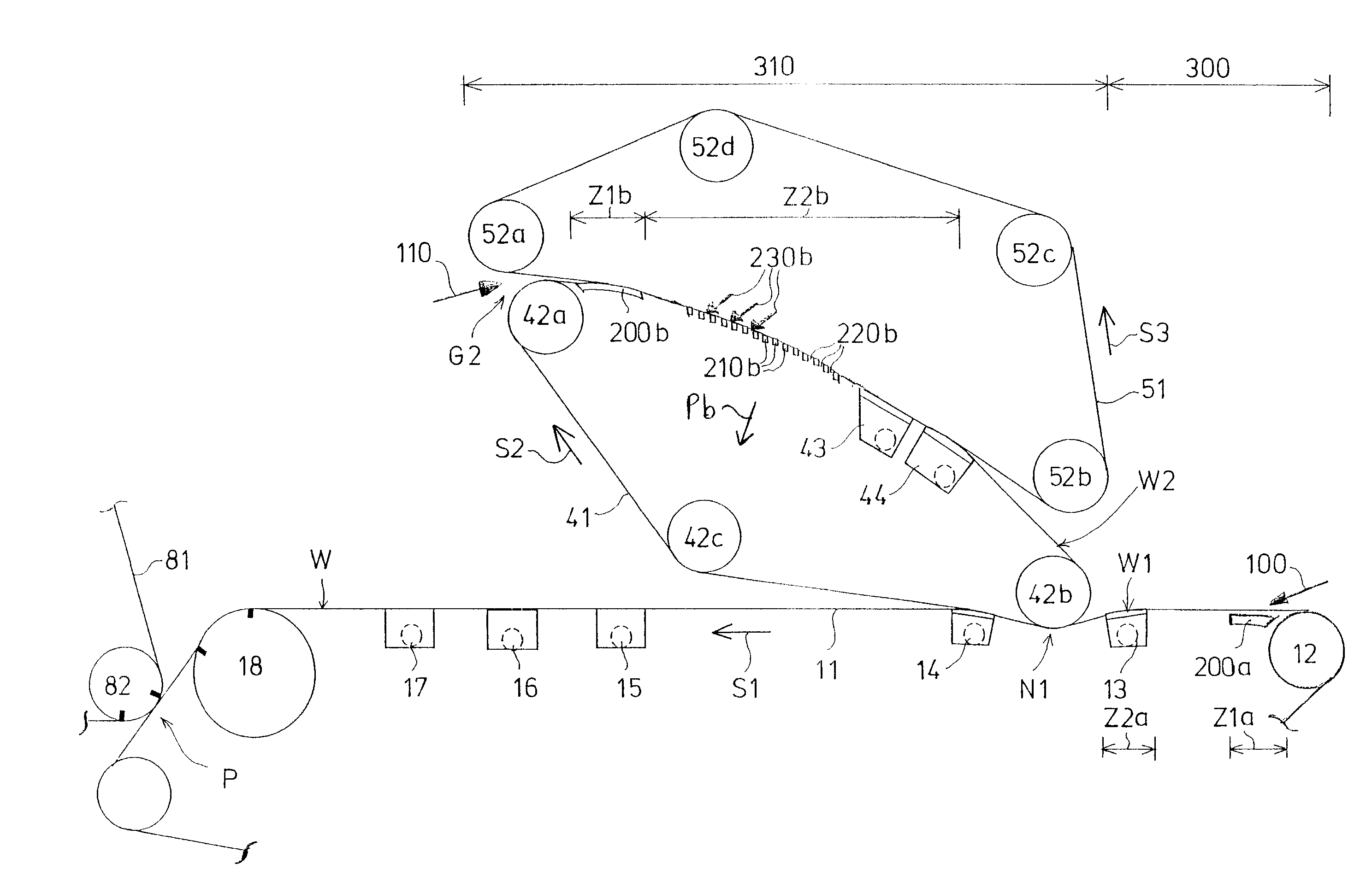
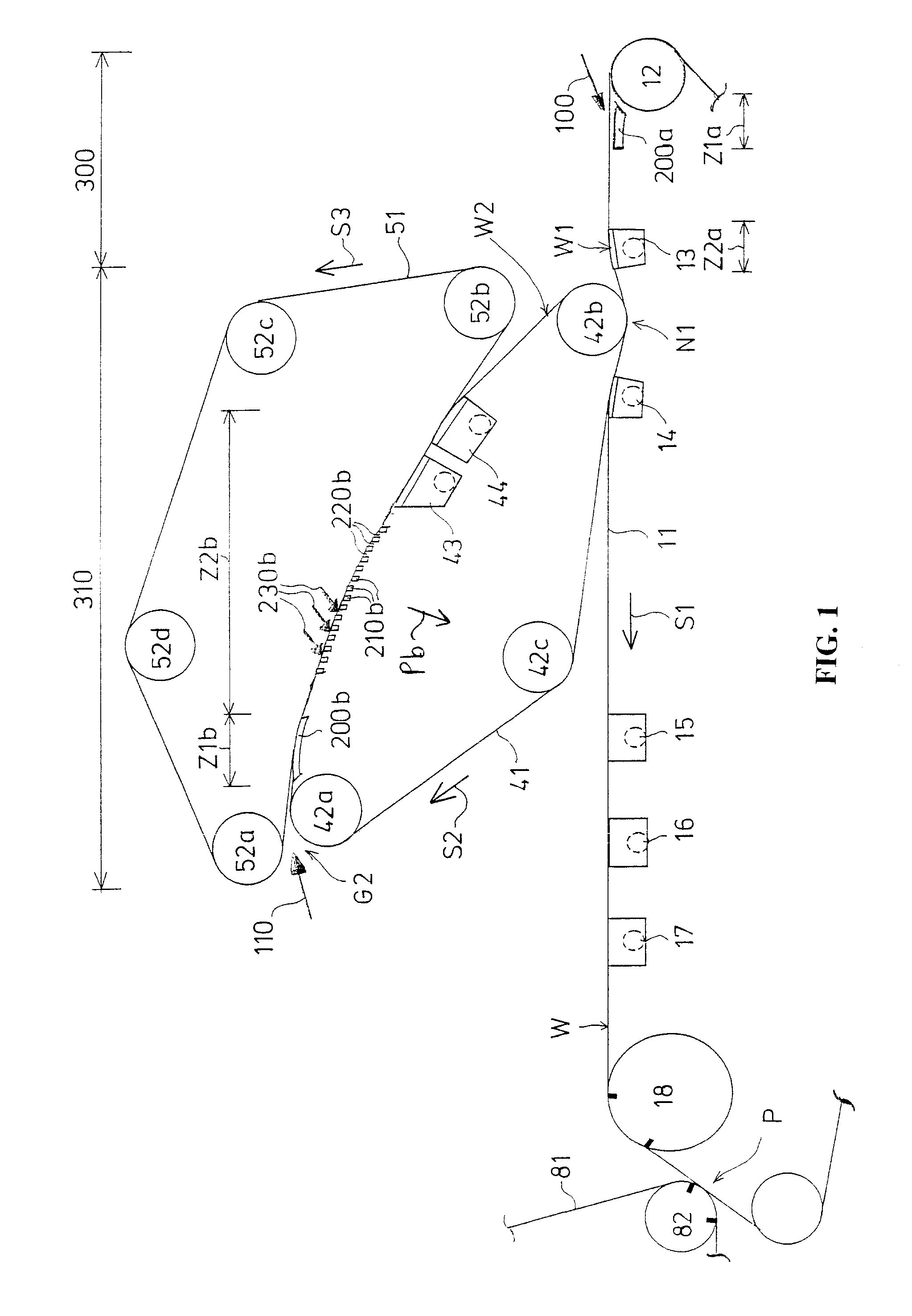
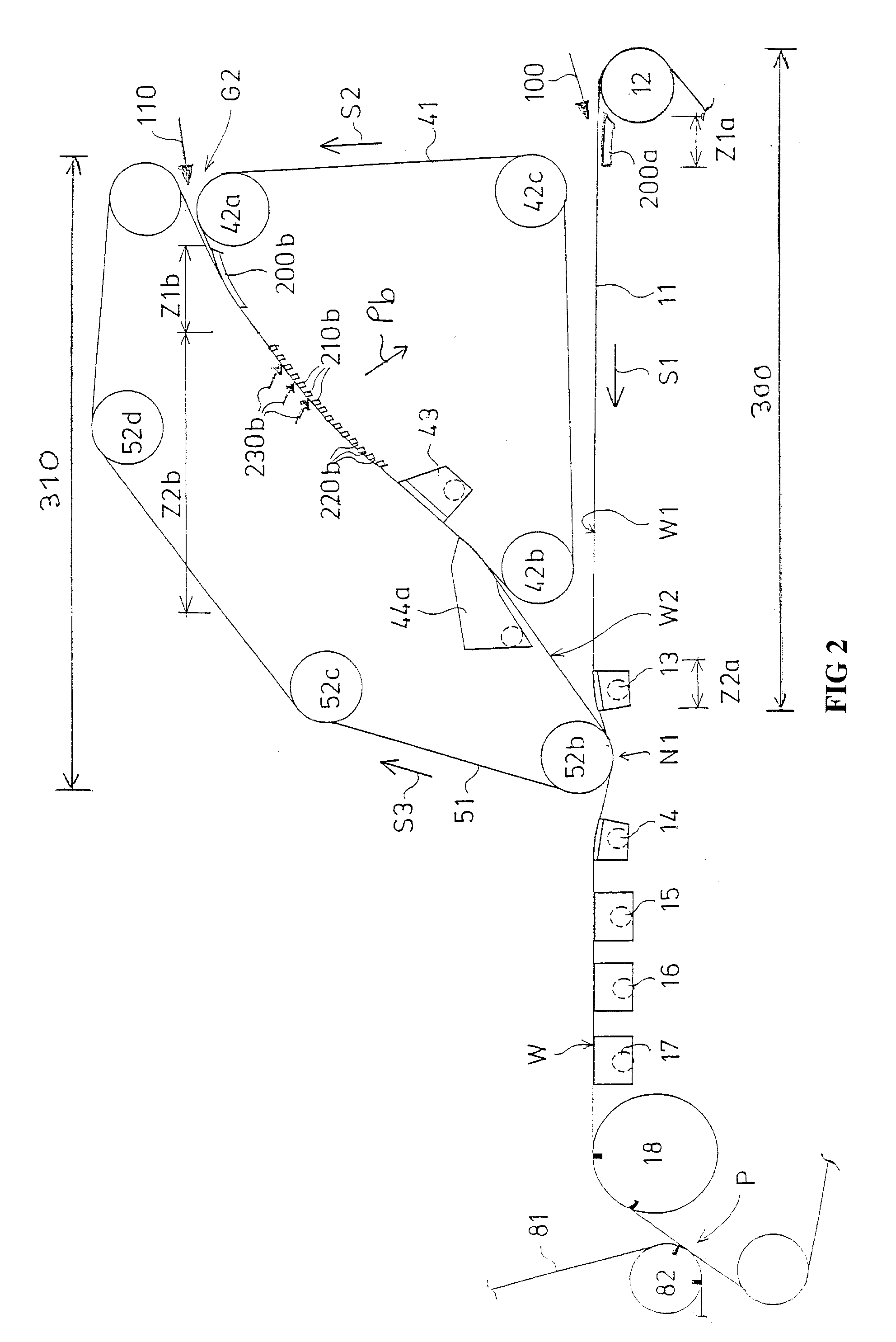
[0038]FIG. 1 shows a formation section according to the invention provided with two successive wire units 300, 310. The first wire unit 300 is a single-wire unit and the second wire unit 310 is a two-wire unit.

[0039] The first wire unit 300 is formed by a bottom wire loop 11 and by dewatering equipment 200a, 13 arranged under the bottom wire 11. A first headbox 100 supplies a pulp suspension jet on to the bottom wire 11 to the forward end of the bottom wire, immediately after a breast roll 12 in order to form a first partial web W1. The travelling direction of the bottom wire 11 is indicated by an arrow S1, so this direction is also the machine direction.

[0040] After the first wire unit 300 there is a second wire unit 310. The second wire unit 310 comprises a first wire 41 made to form an endless wire loop with the aid of hitch rolls and guide rolls 42a, 42b, 42c and a second wire 51 made to form an endless wire loop with the aid of hitch rolls and guide rolls 52a, 52b, 52c, 52d. ...


PUM

PropertyMeasurementUnit
angleaaaaaaaaaa
overlap angleaaaaaaaaaa

Abstract

A multi-layer web formation section has at least two successive wire units (300, 310). First and second headboxes (100, 110) supply pulp suspension jets to the forward end of the first wire unit (300) and the second wire unit respectively to form a first partial web (W1) and a second partial web (W2) which are joined at a joint (N1) between the second wire unit (310) and a bottom wire (11). A first non-pulsating dewatering zone (Z1b) in the forward end of a two-wire stretch of the second wire unit (310) is formed by a fixed formation shoe (200b) having a curved cap (201) placed against one side, having openings with an under-pressure applied. A two-wire stretch of the second wire unit (310) has a second pulsating dewatering zone (Z2b), formed by fixed dewatering lists (210b) in the cross machine direction with gaps (220b) therebetween with an under-pressure (Pb) applied.

Description

CROSS REFERENCES TO RELATED APPLICATIONS [0001] This application is a U.S. national stage application of international app. No. PCT / FI2005 / 050027, filed Feb. 11, 2005, the disclosure of which is incorporated by reference herein, and claims priority on Finnish App. No. 20040225, filed Feb. 13, 2004. STATEMENT AS TO RIGHTS TO INVENTIONS MADE UNDER FEDERALLY SPONSORED RESEARCH AND DEVELOPMENT [0002] Not applicable. BACKGROUND OF THE INVENTION [0003] In the formation section according to the invention, a multi-layer web is made in at least two successive wire units. The first partial web is formed in a first wire unit, which may be a single-wire or a two-wire unit. A second partial web is formed in a second wire unit, which is a two-wire unit. After the first wire unit the first partial web is guided on a bottom wire into a joint, which is located in the area of the second wire unit in between the second wire unit and the bottom wire and wherein the first partial web is joined to the se...

Claims


Application Information

Patent Timeline
Patent Type & Authority Applications(United States)
IPC IPC(8): D21F11/00D21F11/04D21F9/00D21F9/02
CPCD21F9/02D21F9/006
Inventor RAISANEN, KARIPOIKOLAINEN, ANTTI
Owner VALMET TECH INC
Why Eureka
Try Eureka