Liquid slag quick quenching apparatus and method

a liquid slag and quick technology, applied in heat treatment apparatus, furnace types, furnaces, etc., can solve the problems of generating an appreciable amount of dust, difficult handling and transportation of cooled slag in its powder form, and so as to reduce the amount of dust. , the effect of reducing the operating hours of front-end loaders

Inactive Publication Date: 2007-07-12
EXCELL TECH
View PDF19 Cites 0 Cited by
  • Summary
  • Abstract
  • Description
  • Claims
  • Application Information

AI Technical Summary

Benefits of technology

[0018] It is a further object of the present invention to quick quench liquid slag with minimal dust being generated.
[0019] It is yet a further object of the present invention to cool and process liquid slag with a reduction in front-end loader operating hours.

Problems solved by technology

As the liquid slag cools on the ground, it typically turns into a powdery material and generates an appreciable amount of dust.
Handling and transporting the cooled slag in its powder form is typically difficult and may create an unsafe, or hazardous, working environment, especially in windy conditions.

Method used


Image

  • Liquid slag quick quenching apparatus and method
  • Liquid slag quick quenching apparatus and method

Examples


Embodiment Construction

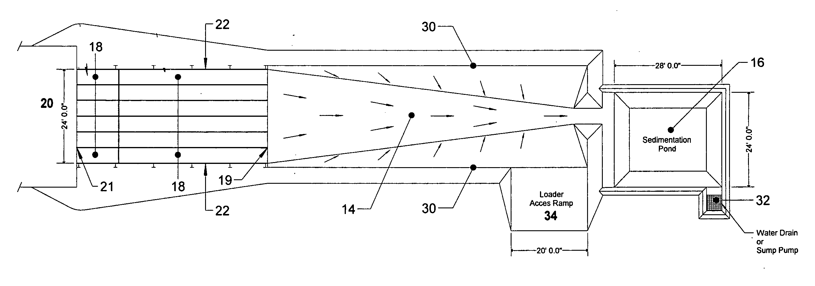
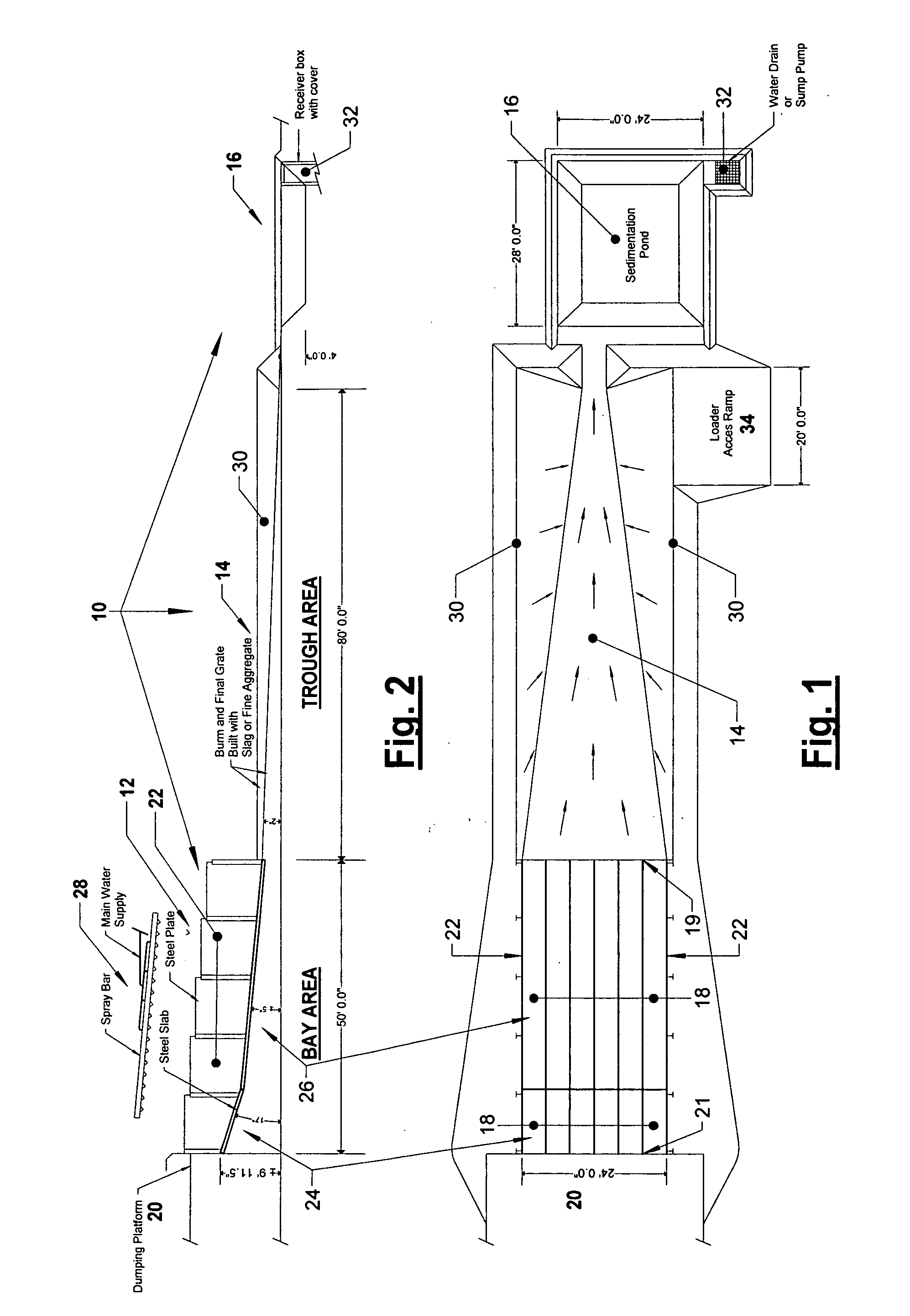
[0023] Referring to FIGS. 1-2, an exemplary apparatus for quick quenching liquid, or molten, slag is illustrated, shown generally at 10. The apparatus 10 generally includes a bay area 12 and a trough area 14. The liquid slag is cooled in the bay area 12 by the application of water under pressure, such that the cooled slag remains in the bay area 12. The trough area 14 receives the water running from the bay area 12 and directs it to a sedimentation pond 16, where the water can be recycled for further quenching or other applications.

[0024] The bay area 12 generally includes a plurality of steel slabs 18 which are installed side by side to form a flat surface. Liquid slag (not shown) is poured onto the steel slabs 18 for cooling, and thus the steel slabs 18 need to be able to withstand the high temperature of the liquid slag. The steel slabs 18 are oriented generally at an angle, with the low end 19 adjacent the trough area 14, such that the liquid slag and the water applied to the l...


PUM

PropertyMeasurementUnit
pressureaaaaaaaaaa
widthaaaaaaaaaa
angle of inclinationaaaaaaaaaa

Abstract

An apparatus and method for quick quenching liquid slag, which includes a bay area for receiving the liquid slag and a water supply system for spraying, or quick quenching, the liquid slag provided on the bay area with water to cool the liquid slag and turn it into a crystalline form. The bay area includes an angled and generally flat surface provided between first and second ends, with the first end defining a high end and the second end defining a low end, such that liquid slag provided to the bay area adjacent the first end will run down the bay area toward the second end. The water supply system is provided operatively above the bay area and applies water to the liquid slag on the bay area such that the liquid slag cools and turns into a crystalline form. Additional amounts of liquid slag may be poured on top of previous cooled and quenched crystalline slag and quick quenched with water in a similar manner.

Description

CROSS-REFERENCE TO RELATED APPLICATIONS [0001] This application claims the benefit of co-pending provisional patent application Ser. No. 60 / 757,434 entitled “Liquid Slag Quick Quenching Apparatus and Method”, filed on Jan. 9, 2006, the entire disclosure of which is incorporated by reference herein.FIELD OF THE INVENTION [0002] The present invention is directed toward an apparatus and method for quenching liquid slag and, more particularly, toward an improved apparatus and method for the quick quenching of liquid slag. BACKGROUND OF THE INVENTION [0003] Slag is a waste byproduct of the steel manufacturing process. Slag is typically generated in molten, or liquid, form by blast furnaces, electric arc furnaces, AOD (Argon Oxygen Decarburisation) furnaces, etc. The slag generated by these furnaces is at an extremely high temperature, and must be cooled in order for it to be able to be easily handled and disposed of or otherwise utilized. [0004] One known method of cooling liquid slag is...

Claims


Application Information

Patent Timeline
Patent Type & Authority Applications(United States)
IPC IPC(8): C21D1/62
CPCC21D1/62
Inventor BERGERON, MARION
Owner EXCELL TECH
Why Eureka
Try Eureka