Fluidising mat, container and container liner with such a mat

a technology of fluidising mats and containers, which is applied in the direction of conveyors, containers, loading/unloading, etc., can solve the problems of high repose angle, difficult flow properties, and large difficulty in discharge from shipping containers, and achieves low cost, low dusting, and easy transportation and installation.

Inactive Publication Date: 2008-11-11
LINERTECH
View PDF23 Cites 5 Cited by
  • Summary
  • Abstract
  • Description
  • Claims
  • Application Information

AI Technical Summary

Benefits of technology

[0022]It is an object of the present invention to resolve the problems associated with conventional fluidising mats referred to hereinabove by providing a low cost fluidising mat which can easily be transported and installed into a shipping container and which will allow such materials to be discharged completely and with minimal dusting.

Problems solved by technology

There are many dry materials in fine particulate form which readily compact and bind together, showing a characteristically high angle of repose and difficult flow properties.
Such powders commonly cause great difficulty on discharge from a shipping container, as they will not flow freely when the container is tipped, even at angles of 45° or more.
Although this known device has succeeded to some degree in facilitating the discharge of fine particulate compactable powders from storage containers, there are a number of disadvantages which have prevented its widespread use.
These disadvantages include:a) The fact that the two flexible layers of the mat lie flat one on top of the other during loading, storage and transport.
However, the ridges created between the pockets commonly trap material making discharge difficult.
Moreover, the separation of the mat into discrete pockets also requires the use of a complex manifold to distribute the air under pressure to each of these pockets.c) Material is commonly trapped between the edge of the fluidising mat and the container walls from where it is difficult to discharge.
Attempts to overcome this problem by extending the fluidising mat up the sides of the container have met with limited success due to creasing problems and the higher initial cost of the mat.d) When the discrete pockets of the fluidising mat are inflated they have a tendency to balloon.
This results in material being trapped down the sides of the fluidising mat from where it is difficult to discharge.
To solve this problem it has been proposed to secure the fluidising mat along its edges to the liner and thereby maintain it at its full width, but this solution has proved complicated, expensive and not very effective.e) The pervasive dusting which follows fluidisation by the high pressure air commonly used in this type of mat generally requires the provision of filtration equipment to reduce the egress of dust into the atmosphere.
Although this fluidising mat provides means for facilitating the discharge of fine particulate compactable powders from storage containers, there are still a number of practical disadvantages which have limited its commercial use.
However, the possibility of ingress of contamination into the liner does in many cases make this totally unacceptable.b) Commercial exploitation of the rigid mat has been further hampered by the high cost of this type of mat.c) The size of the liner and fluidising mat together makes transport difficult, since the rigid mat cannot be folded down in size like the liner.d) The design of the mat with separate longitudinally extending channels requires the use of a relatively complex manifold to connect the open end of each channel to the air supply.

Method used


Image

  • Fluidising mat, container and container liner with such a mat
  • Fluidising mat, container and container liner with such a mat
  • Fluidising mat, container and container liner with such a mat

Examples


Embodiment Construction

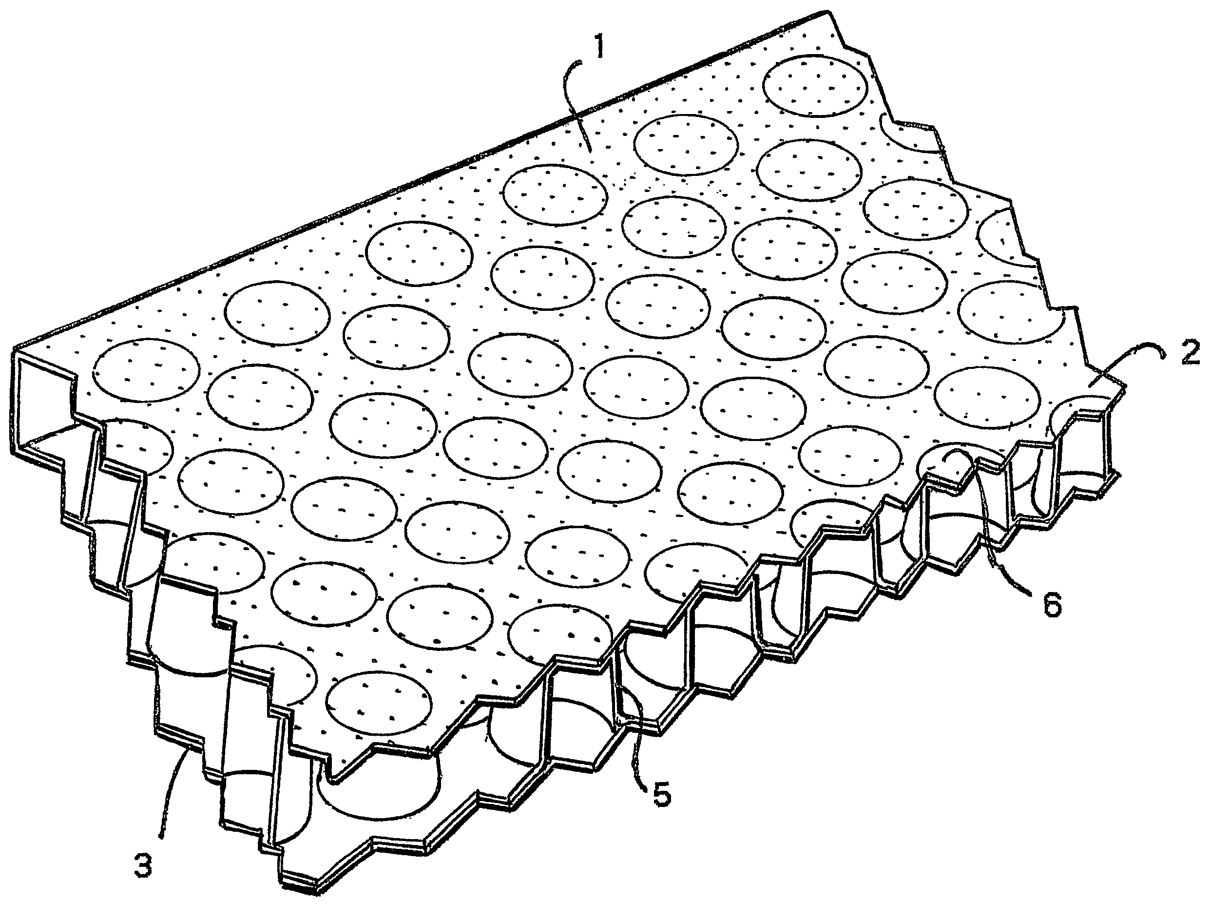
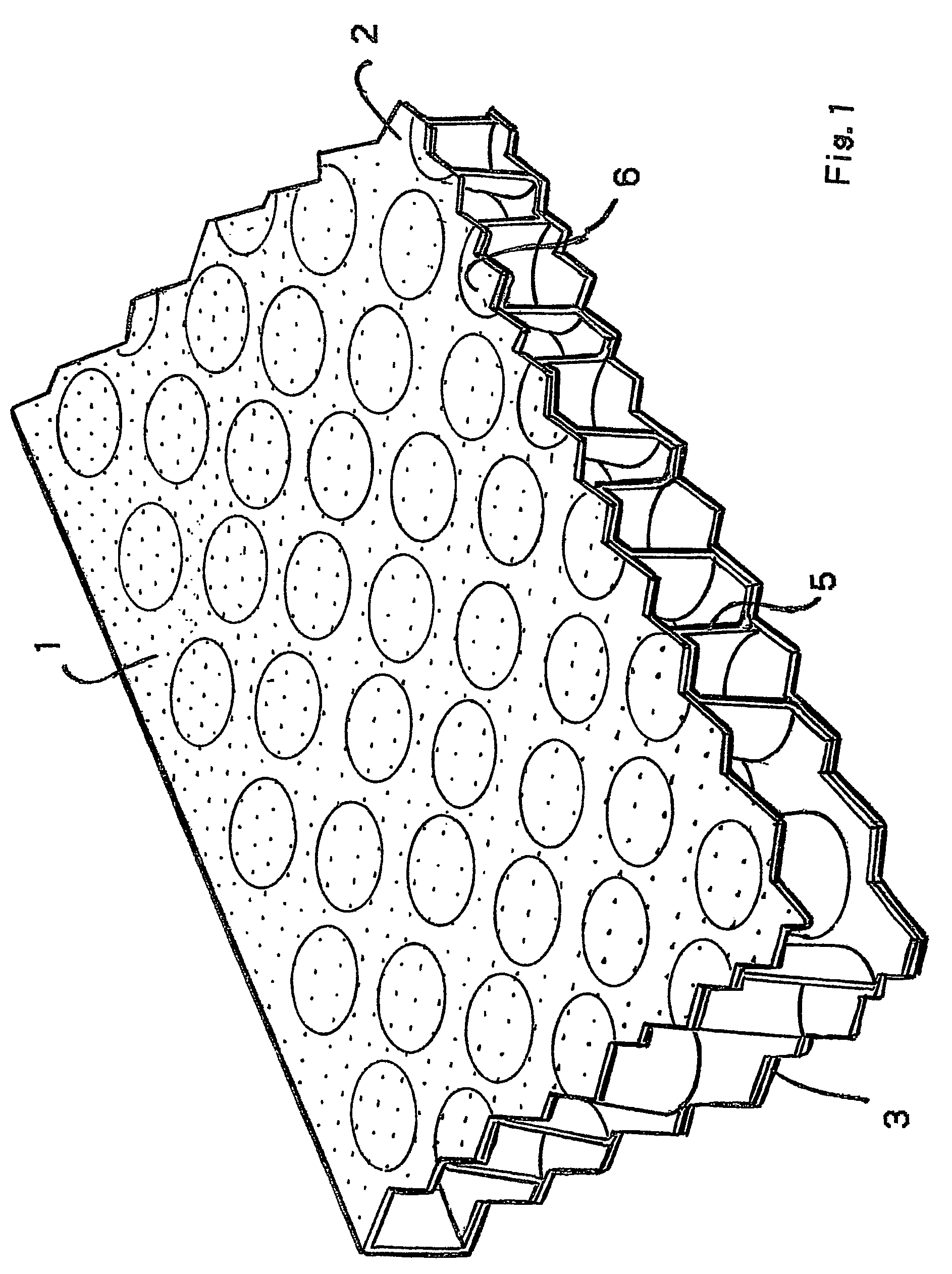
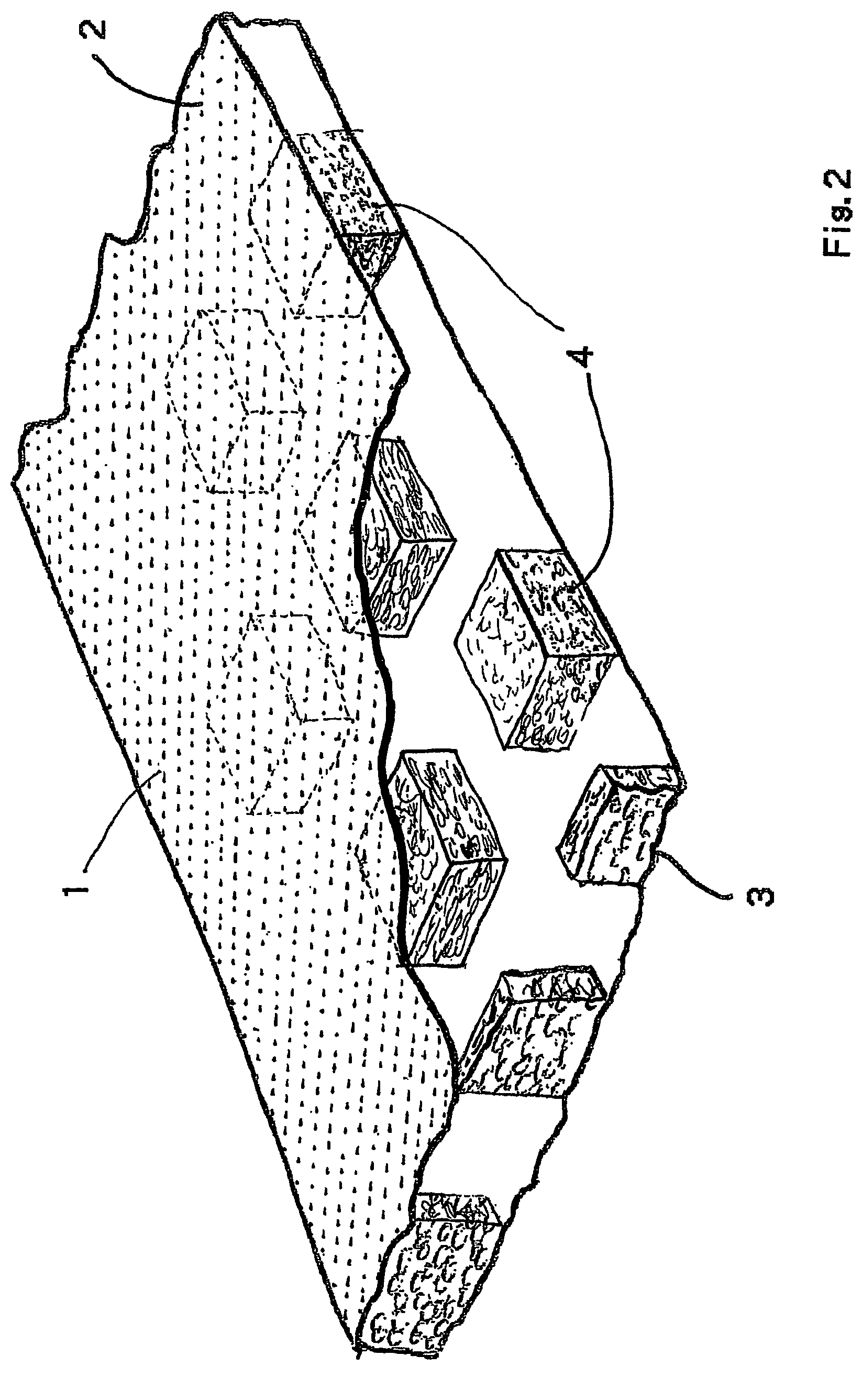
[0048]Referring to FIG. 1 the fluidising mat comprises an upper, flexible sheet 2 of polyethylene or other polymeric material and a flexible gas impermeable lower sheet 3, also of polyethylene or other polymeric material. The upper sheet is rendered gas-permeable by the provision of micro-perforations 1 over the whole surface thereof. The micro-perforations are typically circular typically and of 0.1-0.2 mm diameter and are distributed at a density of typically 35,000 m−1. However, the shape and / or density of the micro-perforations can be adjusted, depending upon the volume of fluidisation gas required for different cohesive powders. The micro-perforations are preferably formed by puncturing using an appropriate diameter needle or other sharp instrument and may conveniently be formed by using a piercing machine or device. However, the micro-perforations may be formed by other means, e.g. by means of a laser. In view of their small size, the micro-perforations are illustrated schemat...


PUM


Abstract

A fluidizing mat has an upper, micro-perforated sheet and a lower gas impermeable sheet. The upper and lower sheets are maintained in spaced apart superimposed relationship by a plurality of spaced-apart load bearing means, e.g. encapsulated air bubbles, which define a plurality of passageways that extend in different directions over substantially the full area of the fluidizing mat and intersect with each other to form a single continuous chamber between the upper and lower sheets.

Description

BACKGROUND OF THE INVENTION[0001]1. Field of the Invention[0002]The present invention relates to container liners used for the transport of compactable, cohesive powders. More specifically the present invention relates to a device for fluidising powdered material contained within a container liner within a shipping container.[0003]2. Background Art[0004]There are many dry materials in fine particulate form which readily compact and bind together, showing a characteristically high angle of repose and difficult flow properties. Such powders commonly cause great difficulty on discharge from a shipping container, as they will not flow freely when the container is tipped, even at angles of 45° or more.[0005]In order to facilitate the discharge of such materials from shipping and other storage containers it is known to fluidise the material by causing air to pass through it.[0006]One known device for achieving fluidisation of powdered materials within a container liner comprises a fluidis...

Claims


Application Information

Patent Timeline
Patent Type & Authority Patents(United States)
IPC IPC(8): B65G53/18B65D88/72
CPCB65D88/72B65G53/18B65G69/06B65D88/00B65G53/04
Inventor BROWN, DAVID MICHAELMASSIE, MICHAEL PETER DOUGLAS
Owner LINERTECH
Why Eureka
Try Eureka