Magnetic resonance imaging system

a magnetic resonance imaging and magnetic field technology, applied in the direction of magnetic variable regulation, measurement using nmr, instruments, etc., can solve the problems of difficult low data acquisition efficiency in time, and inability to obtain high-resolution images. , to achieve the effect of improving data acquisition efficiency and reducing the influence of motion

Active Publication Date: 2007-07-12
TOSHIBA MEDICAL SYST CORP
View PDF5 Cites 40 Cited by
  • Summary
  • Abstract
  • Description
  • Claims
  • Application Information

AI Technical Summary

Benefits of technology

[0013] It is an object of the present invention to reduce the influence of the motion of the heart and motion caused by respiration

Problems solved by technology

Although coronary artery angiography using a CT including multiple rows of detectors, as many as 64 rows or more, i.e., a so-called MDCT (multi-detector row CT), has recently become popular, this examination method poses problems, e.g., a relatively high radiation dose and the use of a contrast medium.
The motion of the heart itself and motion caused by respiration mainly pose problems in obtaining the image information of the heart.
With the speed of MRI at present, it is difficult to obtain a high-resol

Method used


Image

  • Magnetic resonance imaging system
  • Magnetic resonance imaging system
  • Magnetic resonance imaging system

Examples


Embodiment Construction

[0020] An embodiment of the present invention will be described below with reference to the views of the accompanying drawing.

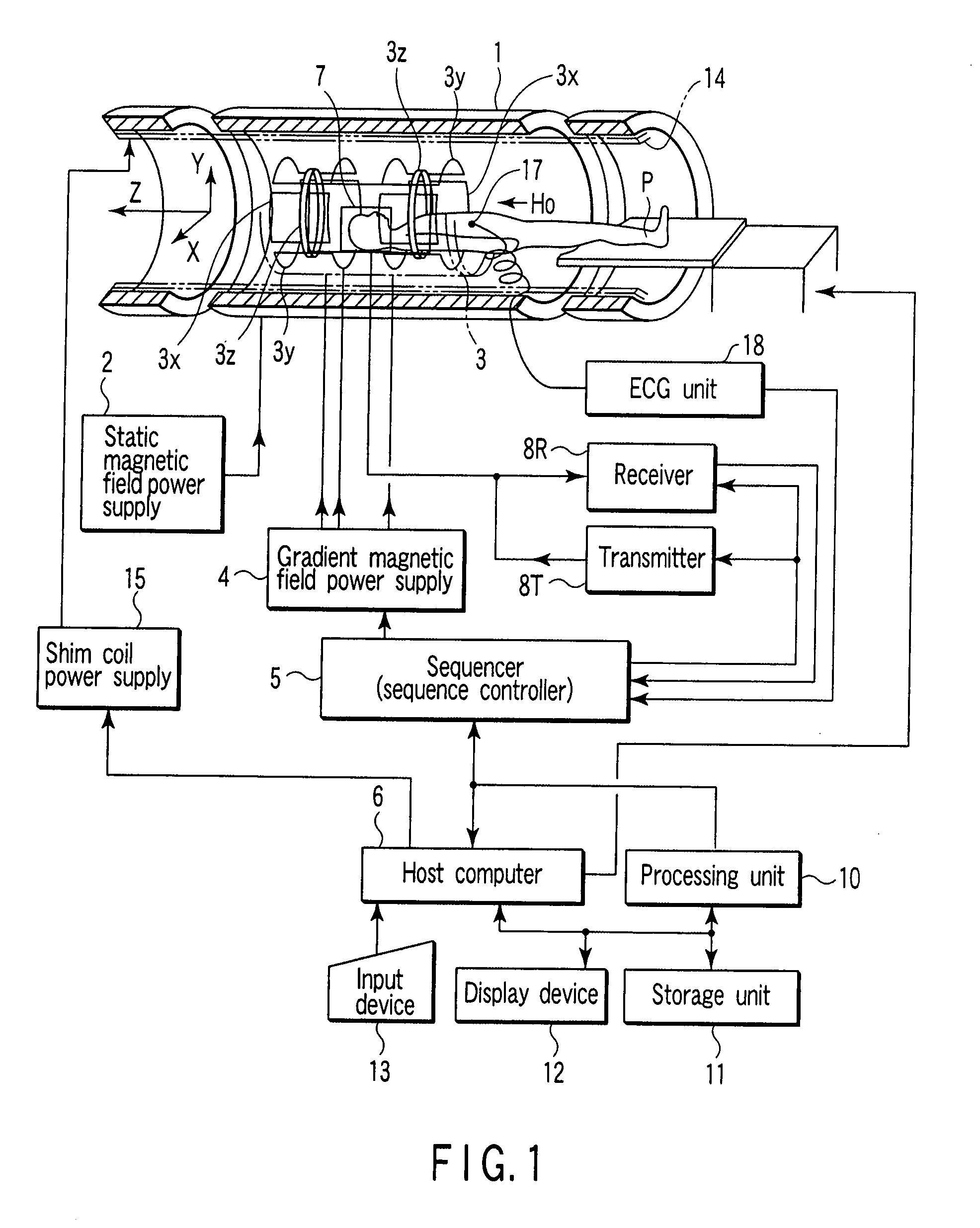
[0021]FIG. 1 shows the schematic arrangement of a magnetic resonance imaging system according to this embodiment. This magnetic resonance imaging system includes a magnetic unit 1 having a cylindrical opening portion (diagnosis space). The magnetic unit 1 receives a current supplied from a static magnetic field power supply 2 and generates a static magnetic field H0 in the opening portion in the Z-axis direction. Typically, the body axis of a subject P inserted in the opening portion almost coincides with the Z-axis. The magnetic unit 1 comprises a shim coil 14. The shim coil 14 receives a current supplied from a shim coil power supply 15 and generates a correction magnetic field for making a static magnetic field uniform. The magnetic unit 1 houses a gradient magnetic field coil unit 3. The gradient magnetic field coil unit 3 comprises three x, y, and z coi...


PUM


Abstract

A magnetic resonance imaging system includes a high-frequency magnetic field generating unit for generating and applying a high-frequency magnetic field to a subject placed in a static magnetic field, a gradient magnetic field generating unit for generating a gradient magnetic field to be superimposed on the static magnetic field, and a sequencer for controlling the high-frequency magnetic field generating unit and the gradient magnetic field generating unit to acquire, within a specified part of the heartbeat of the subject, MR data that pertains to a plane through which an axis substantially identical to the body axis of the subject in a k-space extends, and to cause the plane to rotate, at every heartbeat, about the axis substantially identical to the body axis.

Description

CROSS-REFERENCE TO RELATED APPLICATIONS [0001] This is a Continuation Application of PCT Application No. PCT / JP2005 / 006152, filed Mar. 30, 2005, which was published under PCT Article 21 (2) in Japanese.[0002] This application is based upon and claims the benefit of priority from prior Japanese Patent Application No. 2004-364765, filed Dec. 16, 2004, the entire contents of which are incorporated herein by reference. BACKGROUND OF THE INVENTION [0003] 1. Field of the Invention [0004] The present invention relates to a magnetic resonance imaging system which images a coronary artery. [0005] 2. Description of the Related Art [0006] Although coronary artery angiography using a CT including multiple rows of detectors, as many as 64 rows or more, i.e., a so-called MDCT (multi-detector row CT), has recently become popular, this examination method poses problems, e.g., a relatively high radiation dose and the use of a contrast medium. In a similar method using magnetic resonance imaging (MRI...

Claims


Application Information

Patent Timeline
IPC IPC(8): G01V3/00A61B5/05G01R33/48A61B5/055G01R33/28G01R33/54G01R33/567
CPCG01R33/4822G01R33/4824G01R33/4835G01R33/5676G01R33/5635G01R33/56509G01R33/5673G01R33/5614
Inventor OSHIO, KOICHI
Owner TOSHIBA MEDICAL SYST CORP
Why Eureka
Try Eureka