
Driving system of light emitting diode

a technology of led current and driving system, which is applied in the direction of discharge tube luminescnet screen, static indicating device, instruments, etc., can solve the problems of poor color quality, increased pin number of lcos chip, and increased overall area so as to improve the yield of led current driving system, reduce overall area, and improve the effect of image color quality

Active Publication Date: 2007-07-12
HIMAX DISPLAY INC
View PDF7 Cites 27 Cited by
  • Summary
  • Abstract
  • Description
  • Claims
  • Application Information

AI Technical Summary

Benefits of technology

[0011] Therefore, the LED current driving system of the present invention integrates the LED driver on the LCOS panel, so as to reduce the pin number of the LCOS chip, the overall area, and the system cost, and to improve the yield of the LED current driving system of the present invention. Besides, the LED current driving system of the present invention uses the current sources which are combined into the driving current, so as to stably and precisely control the current flowing through the corresponding LED, and to improve the color quality of the image.

Problems solved by technology

The conventional LED current driving system does not integrate all the elements, so the pin number of the LCOS chip, the overall area, and the system cost are increased.
Moreover, as the integration is not satisfied, the yield of the LED current driving system may be affected.
Besides, the conventional LED current driving system cannot stably and precisely control the current flowing through the LED, so that the color quality is poor.

Method used


Image

  • Driving system of light emitting diode
  • Driving system of light emitting diode
  • Driving system of light emitting diode

Examples


Embodiment Construction

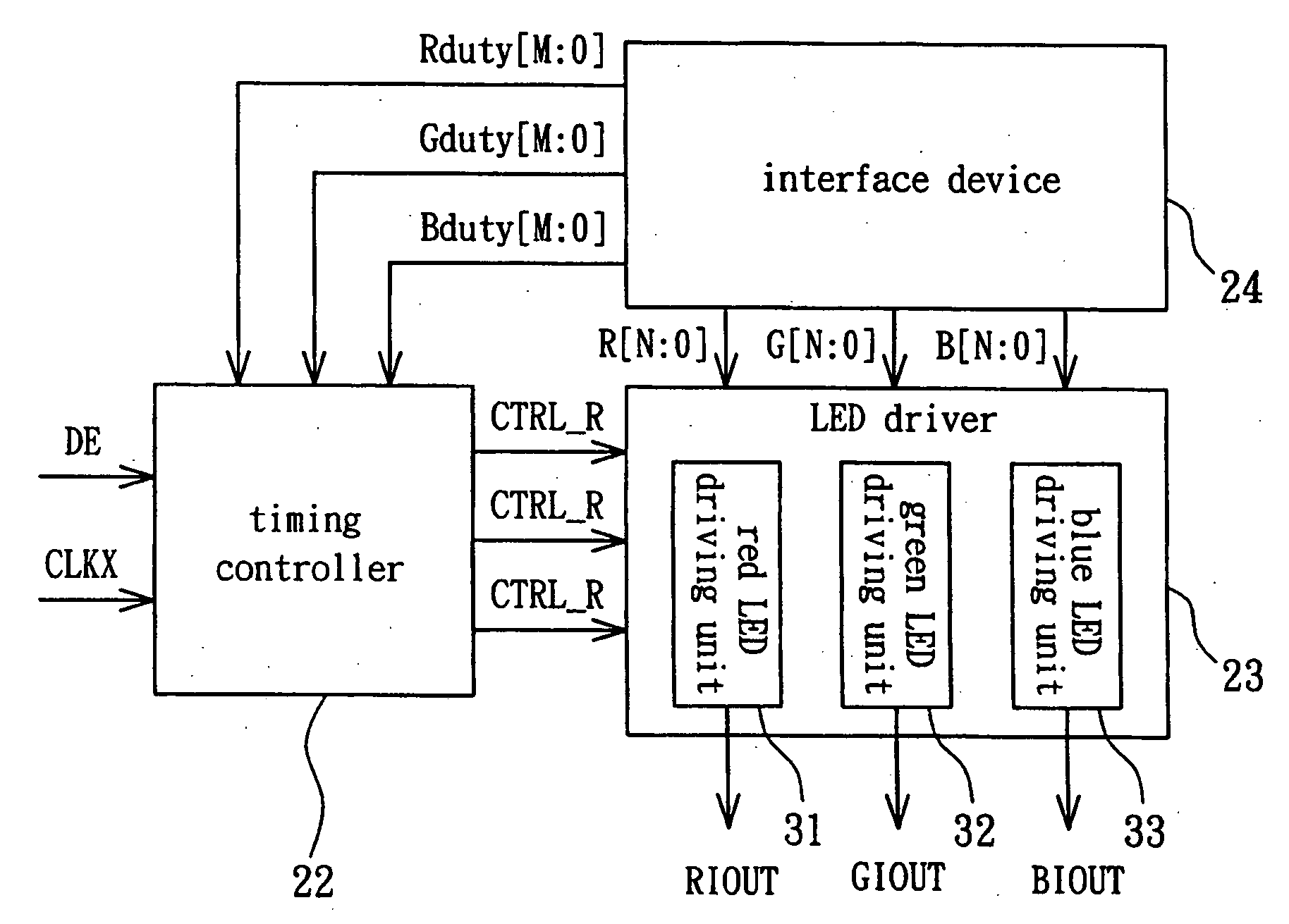
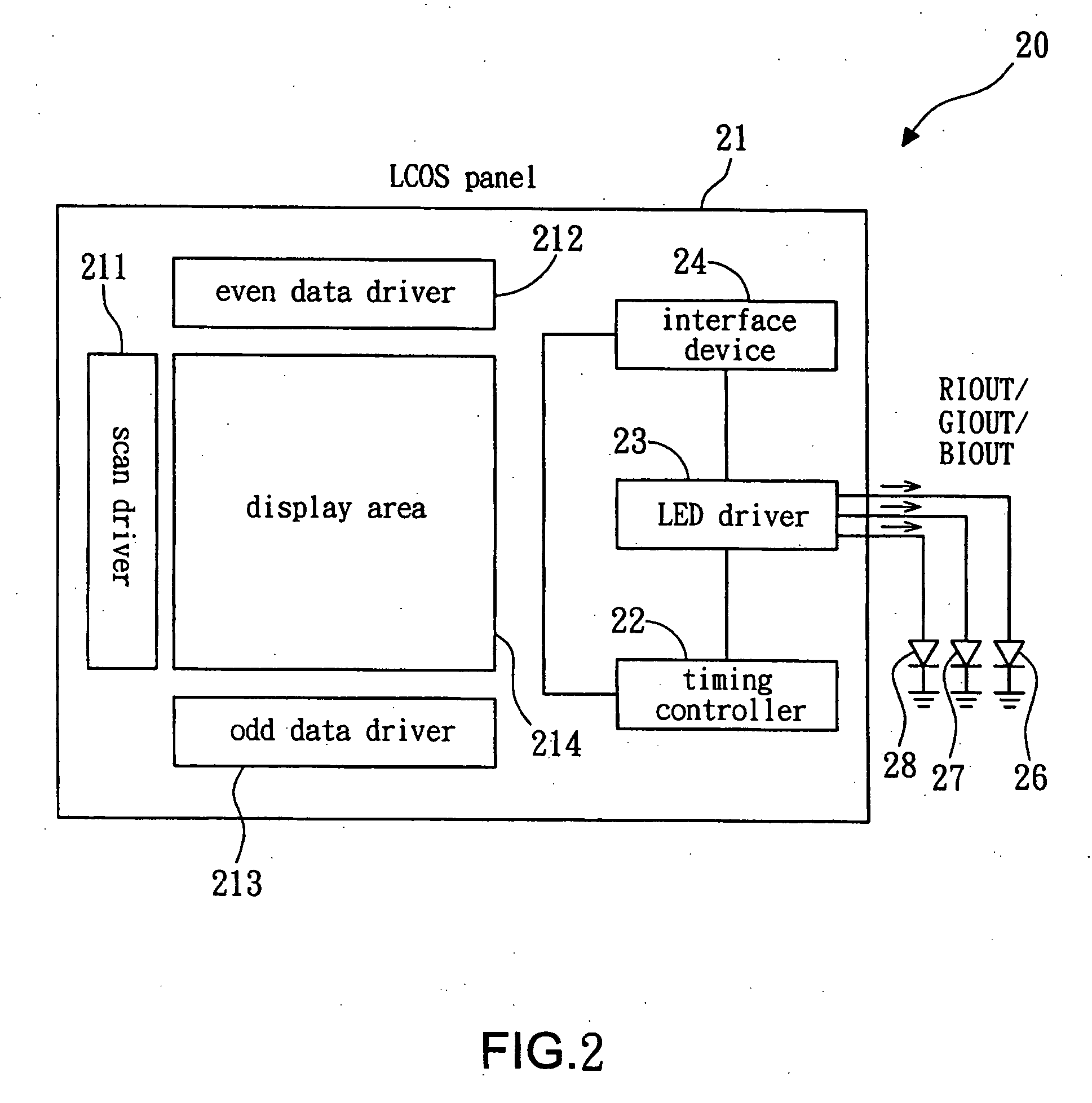
[0019] Referring to FIG. 2, a schematic view of the LED current driving system according to the present invention is shown. The LED current driving system 20 for an LCOS display according to the present invention comprises an LCOS panel 21, a timing controller 22, an LED driver 23, and an interface device 24. The timing controller 22, the LED driver 23, and the interface device 24 are integrated on the LCOS panel 21 for providing the driving current to the LEDs (red, green, and blue LEDs) 26, 27, 28. The LED current driving system of the present invention integrates the LED driver on the LCOS panel, so as to reduce the pin number of the LCOS chip, the overall area, and the system cost, and to improve the yield of the LED current driving system of the present invention.

[0020] The LCOS panel 21 further comprises a scan driver 211, an even data driver 212, an odd data driver 213, and a display area 214. The LCOS panel 21 is used to receive the image data to display image.

[0021] Refer...


PUM


Abstract

The invention relates to an LED current driving system. The LED current driving system comprises an LED driver. The LED driver comprises at least one LED driving unit for outputting a driving current to an LED. Each LED driving unit comprises a plurality of current sources and a plurality of switches. The switches are connected to the corresponding current source. Each switch controls the ON / OFF state of the corresponding current source in accordance with the duty cycle control signal and a current control signal. Therefore, by integrating the LED driver on the LCOS panel, the LED current driving system of the invention can decrease the pin number of the LCOS chip, the overall area and the system cost so as to improve the yield of the LED current driving system. Besides, the LED current driving system utilizes the current sources to form the driving current to stably and precisely control the driving current flowing through the corresponding LED so that the color quality of the image can be improved.

Description

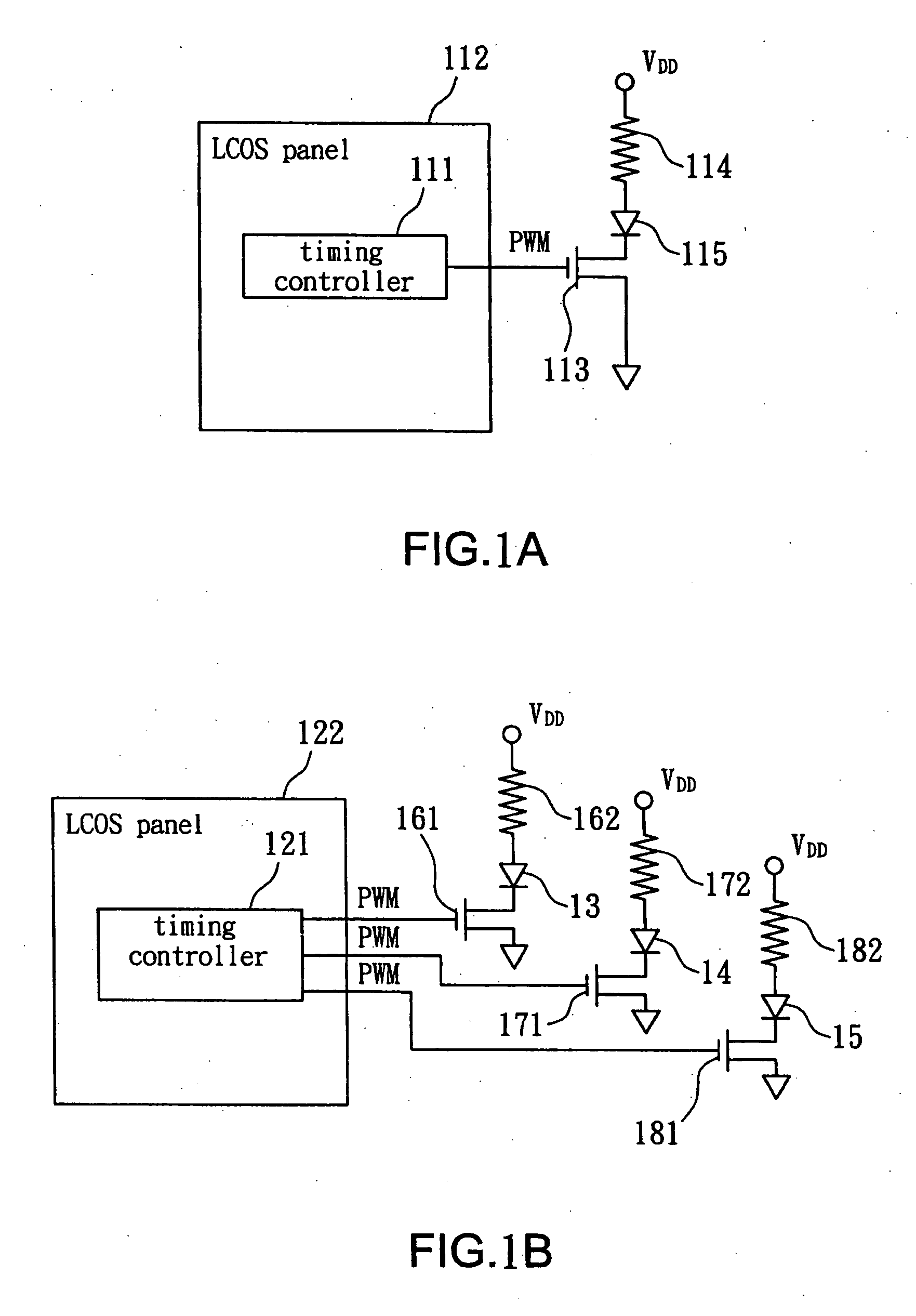
BACKGROUND OF THE INVENTION [0001] 1. Field of the Invention [0002] The present invention relates to an LED (light emitting diode) current driving system. Particularly, the present invention relates to an LED current driving system for an LCOS (liquid crystal on silicon) display. [0003] 2. Description of the Prior Art [0004] Referring to FIGS. 1A and 1B, schematic views of a conventional LED current driving system for an LCOS display are shown. Firstly, referring to FIG. 1A, the conventional LED current driving system 11 includes a timing controller 111, an LCOS panel 112, a transistor 113, and a resistor 114. The conventional LED current driving system 11 is used to control the current of a LED 115. The timing controller 111 is mounted on the LCOS panel 112 for providing a PWM (pulse width modulation) signal to the transistor 113 to control whether the transistor 113 is conducted. According to the ON / OFF states time of the transistor, the magnitude of the current flowing through th...

Claims


Application Information

Patent Timeline
IPC IPC(8): G09G3/36
CPCH05B33/0818Y02B20/347H05B33/086H05B45/20H05B45/397Y02B20/30
Inventor YEN, CHENG-CHIHO, YUNG-YUANCHEN, YEN-CHEN
Owner HIMAX DISPLAY INC
Learn More