Multi-level power converter

a power converter and multi-level technology, applied in power conversion systems, emergency protective arrangements for limiting excess voltage/current, electrical equipment, etc., can solve the problems of difficulty in adjusting the delay time, difficulty in detecting abnormally high voltage between the positive and negative terminals of the switching element, and time-consuming and labor-intensive problems, to achieve the effect of high reliability

Active Publication Date: 2007-07-12
TOSHIBA MITSUBISHI-ELECTRIC IND SYST CORP
View PDF8 Cites 35 Cited by
  • Summary
  • Abstract
  • Description
  • Claims
  • Application Information

AI Technical Summary

Benefits of technology

[0012] An advantage of an aspect of the present invention is to provide a multi-level power converter that can detect an over-current failure caused by main circuit elements more rapidly and with high reliability.

Problems solved by technology

But the delay of time is needed to accomplish an over-current protection of the equipment as mentioned above.
Further, it is difficult to adjust the delay time.
Furthermore, in a free-back mode at a middle part of the switching leg, it is difficult to detect an abnormally high voltage between positive and negative terminals of a switching element during a period of its ON-state, because positive current does not flows through the switching element at that time.

Method used


Image

  • Multi-level power converter
  • Multi-level power converter
  • Multi-level power converter

Examples


first embodiment

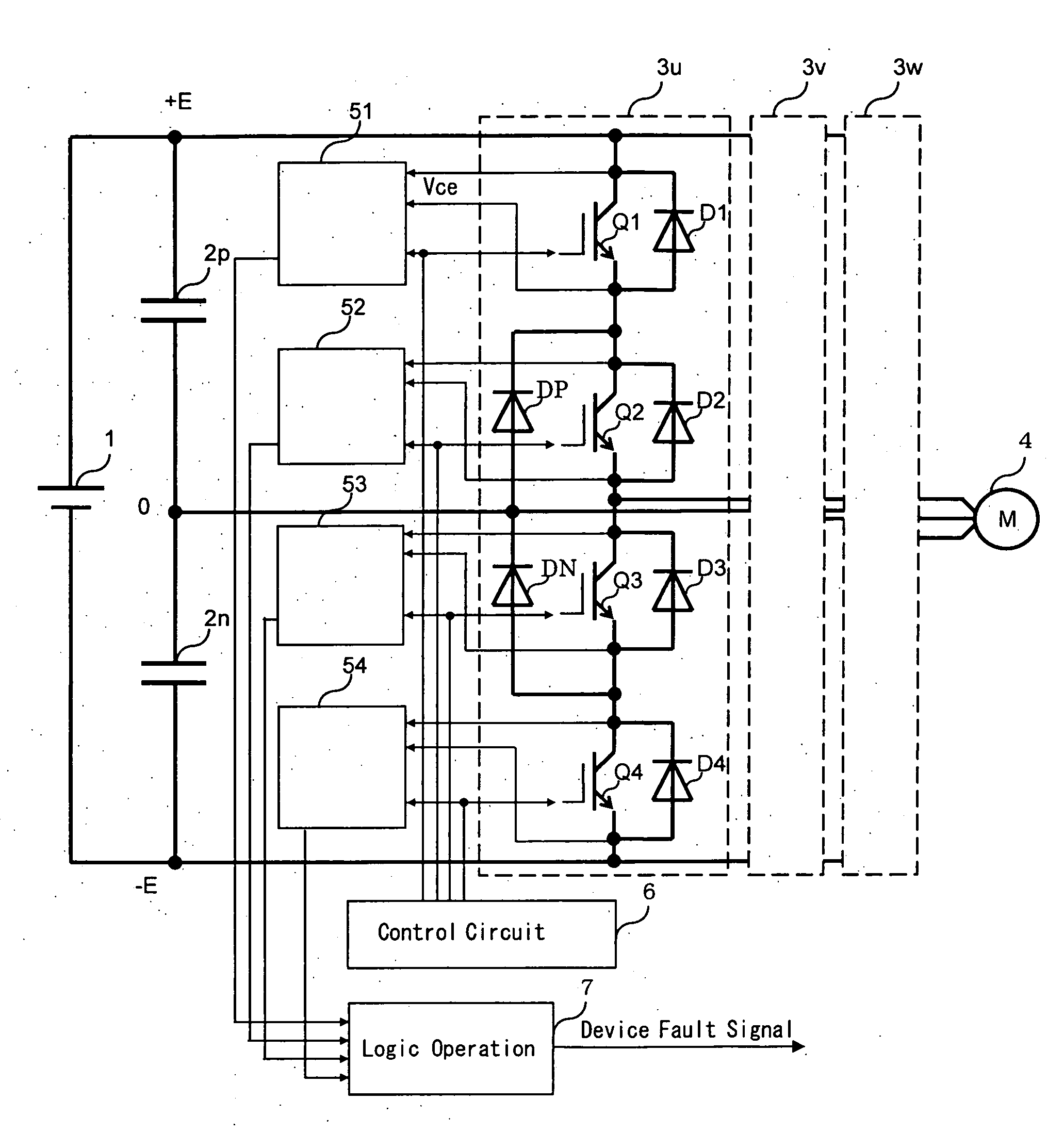
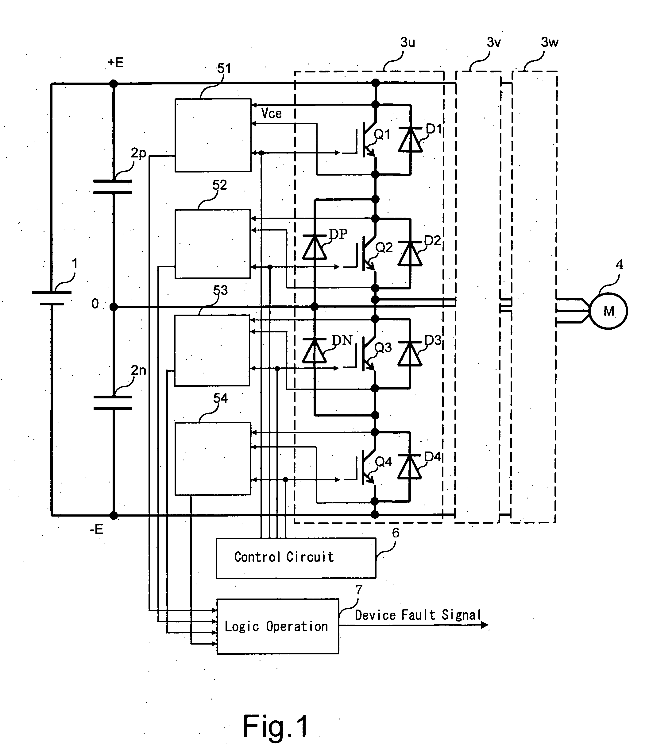
[0027] With reference to FIGS. 1 to 7, a multi-level power converter of the first embodiment according to the invention is explained. FIG. 1 shows a circuit diagram of the power converter relating to the first embodiment of the present invention.

[0028] A DC voltage obtained from a DC power supply 1 is supplied to a series circuit consists of DC capacitors 2p and 2n having same capacitance. The DC power supply 1 has the voltage of 2E. Therefore, when positive side voltage potential of DC capacitor 2p is +E, negative side voltage potential of DC capacitor 2n is −E, and a voltage potential of central terminal of the DC capacitors 2p and 2n is 0 potential.

[0029] These three voltage potentials +E, −E and 0 are supplied to the switching legs 3u, 3v, and 3w. In FIG. 1, the internal composition of switching leg 3u is illustrated. Since the internal composition of other switching legs 3v and 3w are fundamentally same composed as that of switching leg 3u, those illustrations and explanation...

second embodiment

[0046] With reference to FIGS. 8 to 11, a multi-level power converter of a second embodiment according to the invention is explained. FIG. 8 shows an internal circuit diagram of a voltage detector 51A applied to the second embodiment of the multi-level power converter according to the present invention.

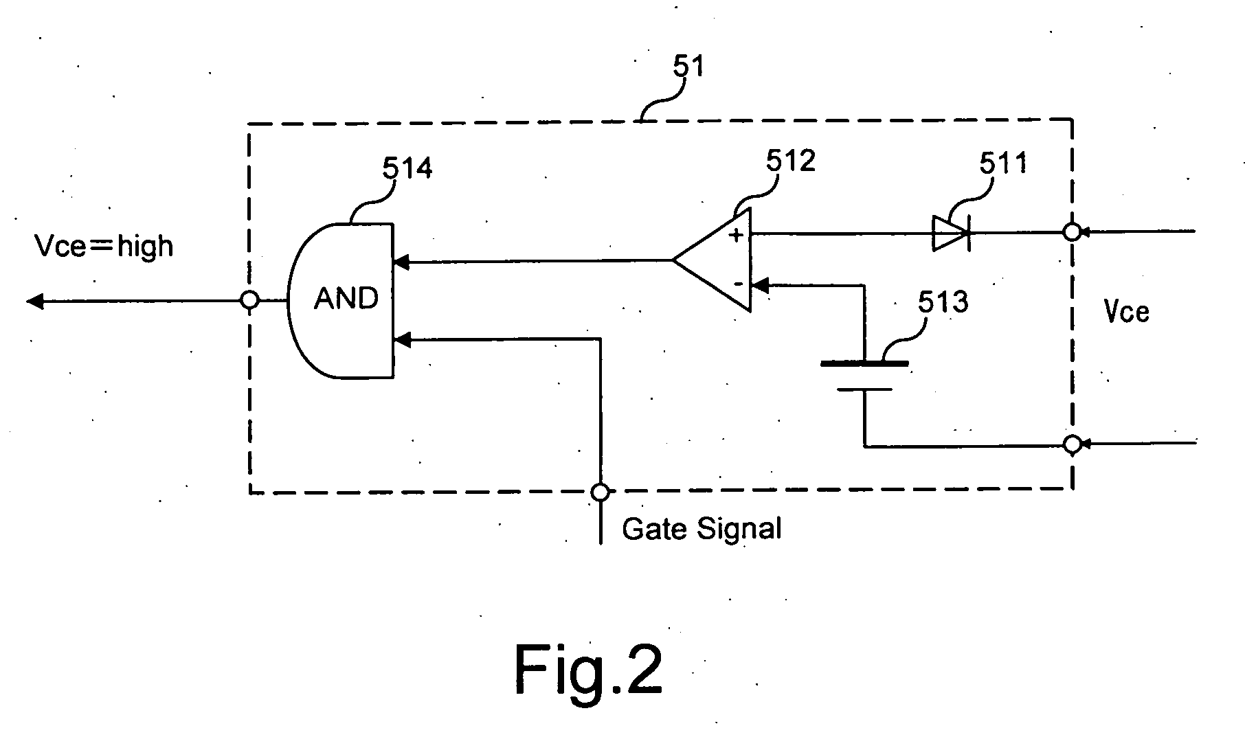
[0047] To the same parts of the second embodiment as those shown in the circuit diagram of the voltage detector 51 relating to the first embodiment shown in FIG. 2, the same numerals are assigned and the explanation thereof will be omitted. In the second embodiment, a time delay circuit 515 is inserted at the output side of the comparator 512 in the voltage detector 51A and the output of the time delay circuit 515 might be given to AND circuit 514.

[0048] As mentioned above, the time delay circuit 515 protects an incorrect detection during a transient state when the switching element Q1 turns on. Since voltage Vce is over the threshold level irrespective of an existence of the over-c...

third embodiment

[0057] With reference to FIGS. 12 and 13, a multi-level power converter of a third embodiment according to the invention is explained. FIG. 12 shows an internal circuit diagram of a voltage detector 51B applied to the third embodiment of the multi-level power converter according to the present invention.

[0058] To the same parts of the third embodiment as those shown in the circuit diagram of the voltage detector 51A relating to the second embodiment shown in FIG. 8, the same numerals are assigned and the explanation thereof will be omitted. In the third embodiment, an AND circuit 514A is added to the voltage detector 51A relating to the second embodiment shown in FIG. 8. A direct output signal from the comparator 512 and the gate signal are inputted to the AND circuit 514A.

[0059] Therefore, a voltage detector 51B outputs two signals with time delay and without time delay as the voltage Vce “high” signal of the switching element during a period of its ON-state. In the case of the t...


PUM


Abstract

A multi-level power converter is disclosed. The converter includes a DC power source having N (N is an Integer more than two)-level voltage potentials, and a plurality of switching legs connected in parallel to the DC power source. The switching leg has switching elements in series connection, and clamp diodes connected between intermediate DC potential terminals to middle points of the switching legs. The converter is provided with a control means for supplying gate pulses to the switching elements, and a supervising means for supervising every switching element to output a failure signal. The converter further includes a logic operating means for detecting an over-current failure of main circuit elements to output a device fault signal using the failure signals An operation of the logic operating means at least includes AND condition of at least two failure signals to output the device fault signal.

Description

CROSS REFERENCE TO RELATED APPLICATION [0001] This application is based upon and claims the benefit of priority from the prior Japanese Patent Application No. 2006-002375, filed on Jan. 10, 2006, the entire contents of which are incorporated herein by reference. BACKGROUND OF THE INVENTION [0002] 1. Field of the Invention [0003] The present invention relates to a multi-level power converter which has an improved detection function of an over-current failure. [0004] 2. Description of the Background [0005] A two-level inverter has been used as a power converter to change a DC power into an AC power. Recently, needs of large capacity power converter with high voltage are expanded. So-called multi-level inverter equipment having three or more voltage potentials become to be used for example, for a motor drive application. [0006] Three-level inverter equipment is one which outputs three DC voltage potentials. On the other hand, the conventional two-level inverter equipment outputs two DC...

Claims


Application Information

Patent Timeline
Patent Type & Authority Applications(United States)
IPC IPC(8): H02H9/02
CPCH02M7/487
Inventor OKA, TOSHIAKI
Owner TOSHIBA MITSUBISHI-ELECTRIC IND SYST CORP
Why Eureka
Try Eureka