Metal cutting tool and cutting plate provided in the shape of a donut

a technology of cutting plate and metal cutting tool, which is applied in the direction of turning apparatus, metal-working apparatus, turning machine accessories, etc., can solve the problems of stress in the cutting plate, lack of form-locking connection with the supporting tool with respect to the clamping force, and even breakag

Inactive Publication Date: 2007-07-12
CERAMTEC
View PDF29 Cites 17 Cited by
  • Summary
  • Abstract
  • Description
  • Claims
  • Application Information

AI Technical Summary

Benefits of technology

[0019] The formation as an indexa

Problems solved by technology

The disadvantage of this technology in the case of smooth cutting plate surfaces is the lack of a form-locking connection with the supporting tool with respect to the clamping force.
In the case of cutting plates that have a clamping trough admittedly there is in addition a form-locking connection, but as a result of the clamping in the clampi

Method used


Image

  • Metal cutting tool and cutting plate provided in the shape of a donut
  • Metal cutting tool and cutting plate provided in the shape of a donut
  • Metal cutting tool and cutting plate provided in the shape of a donut

Examples


Embodiment Construction

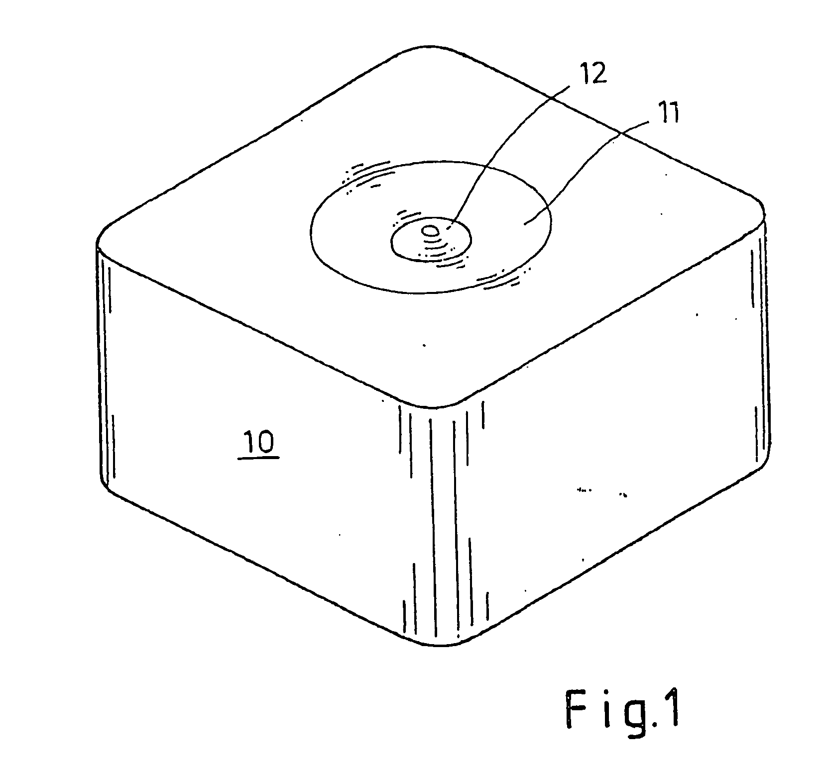
[0035]FIG. 1 shows a cutting insert or a cutting plate 10 as an indexable cutting plate for the metal-removing processing of metallic work pieces. The cutting plate 10 has in the centre a circular clamping trough 11, with there being positioned in turn in the centre of the latter a spherical or circular elevation 12. This clamping trough 11 and elevation 12 are to be used to fix the cutting plate in an appropriate receiver, here called a plate seat, on a suitable supporting tool.

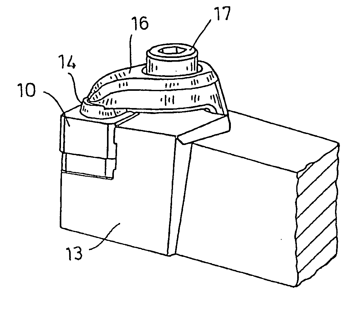
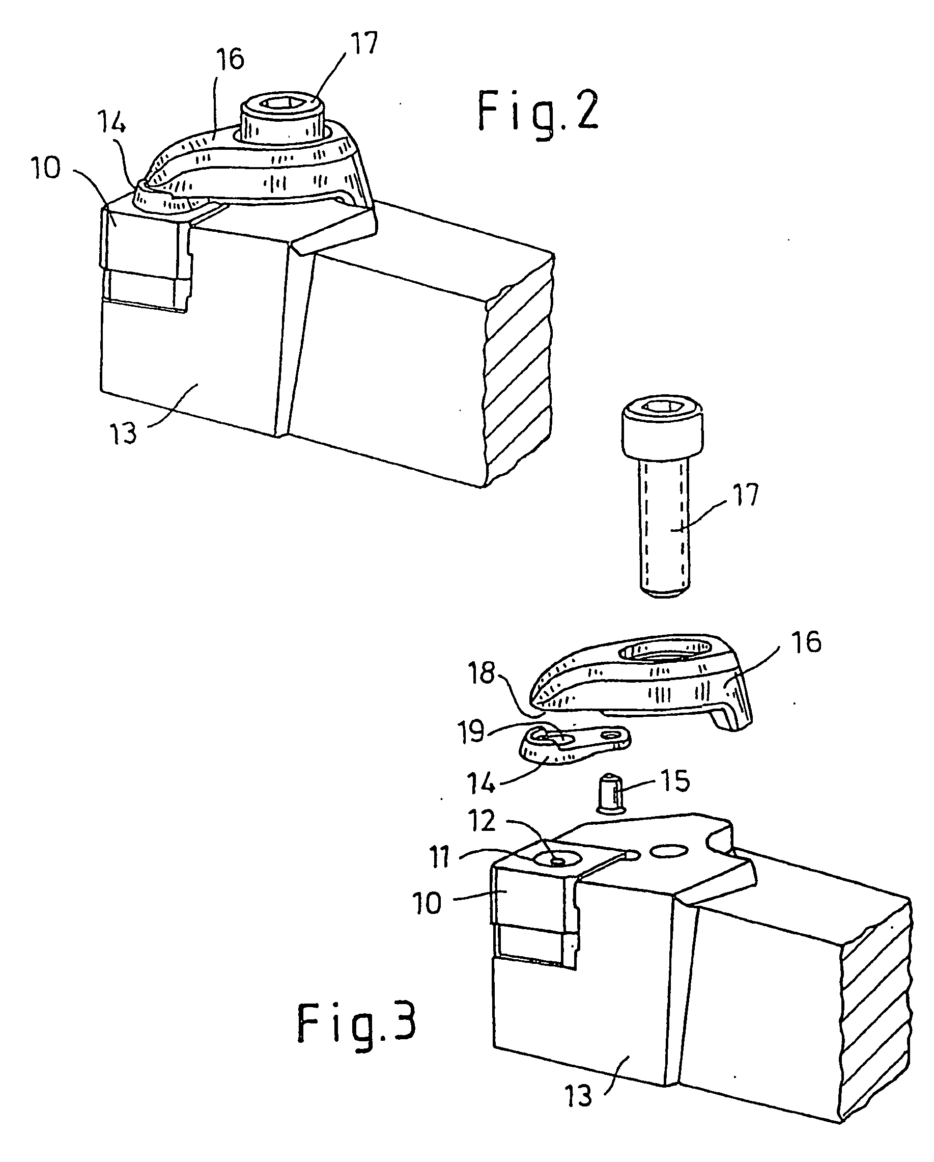
[0036]FIG. 2 shows the spatial representation of the cutting plate 10 that has been described in the clamped state on a supporting tool 13. Special attention is to be given in this connection to the pressure piece 14 (see also FIG. 3) which on the underside has the counter-form of the clamping trough in the cutting plate previously described. The clamping force that develops as a result of tightening the clamping screw 17 is transferred by way of the clamping claw 16 to the cutting plate 10. As a special fe...


PUM

PropertyMeasurementUnit
Angleaaaaaaaaaa
Angleaaaaaaaaaa
Forceaaaaaaaaaa

Abstract

A metal cutting tool has a supporting tool, which has a recess for accommodating a cutting plate. The cutting plate is provided with a clamping trough, which is held in the supporting tool by a clamping claw. The clamping claw is fixed against the supporting tool by a clamping screw. A pressure piece is placed on the clamping claw and its underside facing the cutting plate is provided with a cam, which is in contact with the clamping trough and the clamping claw pulls the pressure piece toward the clamping screw.

Description

[0001] This application is a continuation application of U.S. Ser. No. 10 / 483,886 filed Jun. 10, 2004, incorporated by reference in its entirety, which is a §371 of PCT / DE02 / 02665 filed Jul. 19, 2002, which claims priority from German Patent Application No. 101 36 635.3 filed Jul. 26, 2001 and German Patent Application No. 102 08 266.9 filed Feb. 26, 2002.[0002] The invention relates to a metal-cutting tool in accordance with the preamble of claim 1 and an associated cutting plate. [0003] The prior art for a cutting insert, here an indexable cutting plate made of ceramic material, is constituted by cutting plates that have a smooth surface or that have a great variety of clamping troughs and are inserted so as to be clamped in a supporting tool for the purpose of machining metallic materials. The disadvantage of this technology in the case of smooth cutting plate surfaces is the lack of a form-locking connection with the supporting tool with respect to the clamping force. In the cas...

Claims


Application Information

Patent Timeline
IPC IPC(8): B23P15/28B23B27/16
CPCB23B27/1629B23B27/1644B23B27/1625Y10T407/2282Y10T407/2286Y10T29/49948Y10T407/23B23B27/16
Inventor EDER, OTTOZITZLAFF, WOLFGANG
Owner CERAMTEC
Why Eureka
Try Eureka