Stiffening element and a method for manufacturing of a stiffening elememt

a technology of stiffening elememt and stiffening element, which is applied in the field of stiffening element and a manufacturing method of stiffening elememt, can solve the problems of difficult to provide fibre material, manual work for application of prepreg material, and time-consuming to form aircraft ribs comprising webs and flanges of composite materials. , to achieve the effect of reducing the weight of the stiffening element, reducing the weight of the stiffen

Inactive Publication Date: 2007-07-12
SAAB AB
View PDF10 Cites 41 Cited by
  • Summary
  • Abstract
  • Description
  • Claims
  • Application Information

AI Technical Summary

Benefits of technology

[0006] Thereby a plain blank of plastic layers (composite material) having a curved extension in the plane of the blank, can be used cost-effectively for producing composite material with a curvature following the curvature of the curved shell surface. The laying of plastic layers onto a flat blank building surface (creating a flat lay-up of plastic) is cost effective. The plastic material being curable, such as thermosetting resin. Each plastic layer preferably comprises reinforcement elements, for example carbon / glass or aramid fibres. Different layers may have fibres aligned in different directions. The outer flange or fixation flange is to be attached to the inner curved shell surface. By folding the flat blank along a three-dimensional folding line (the first folding line) the structure of the bank can be preserved without any wrinkles and discontinuous fibre directions of the blank.
[0030] Thereby the strength of the stiffening element is increased, since large bending loads are to be carried by the bracing means.

Problems solved by technology

It is today time-consuming to form an aircraft rib comprising a web and flanges of composite material.
Manual work for application of prepreg material is required since it is difficult to provide that the fibre material follows the curvature of the rib or frame.
Especially Z-shaped and Ω-shaped ribs of composite are difficult to manufacture since the fibre material tend to not follow the curvature.
The method disclosed may enable manufacturing times and costs to be reduced, but involves a complicated procedure and usage of fibre material to achieve the composite material.

Method used


Image

  • Stiffening element and a method for manufacturing of a stiffening elememt
  • Stiffening element and a method for manufacturing of a stiffening elememt
  • Stiffening element and a method for manufacturing of a stiffening elememt

Examples


first embodiment

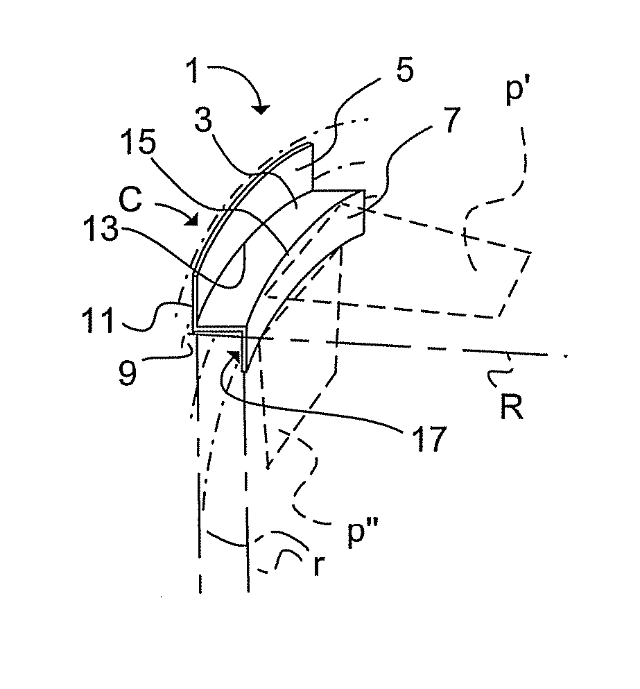
[0048] Referring to FIG. 1a, a stiffening element 1 of composite material or plastic, such as thermosetting resin, comprises a web 3 and an outer 5 (first flange or fixation flange) and inner 7 (second flange or free flange) flange according to a The outer flange 5 is provided for attachment to a single curved shell surface 9. An outer surface 11 of the outer flange 5 has a radius R of curvature corresponding with the radius of the curvature of the single curved shell surface 9. The inner flange 7 has a curvature parallel with the curvature of the outer flange 5. A first folding line 13 is provided between the outer flange 5 and the web 3. A second folding line 15 is provided between the inner flange 7 and the web 3. The second folding line 15 has a radius of curvature parallel with the radius of curvature of the first folding line 13. The extension of the outer flange 5 is parallel with the extension of the inner flange 7. The curvature of a surface 17 of the inner flange 7 facing...

second embodiment

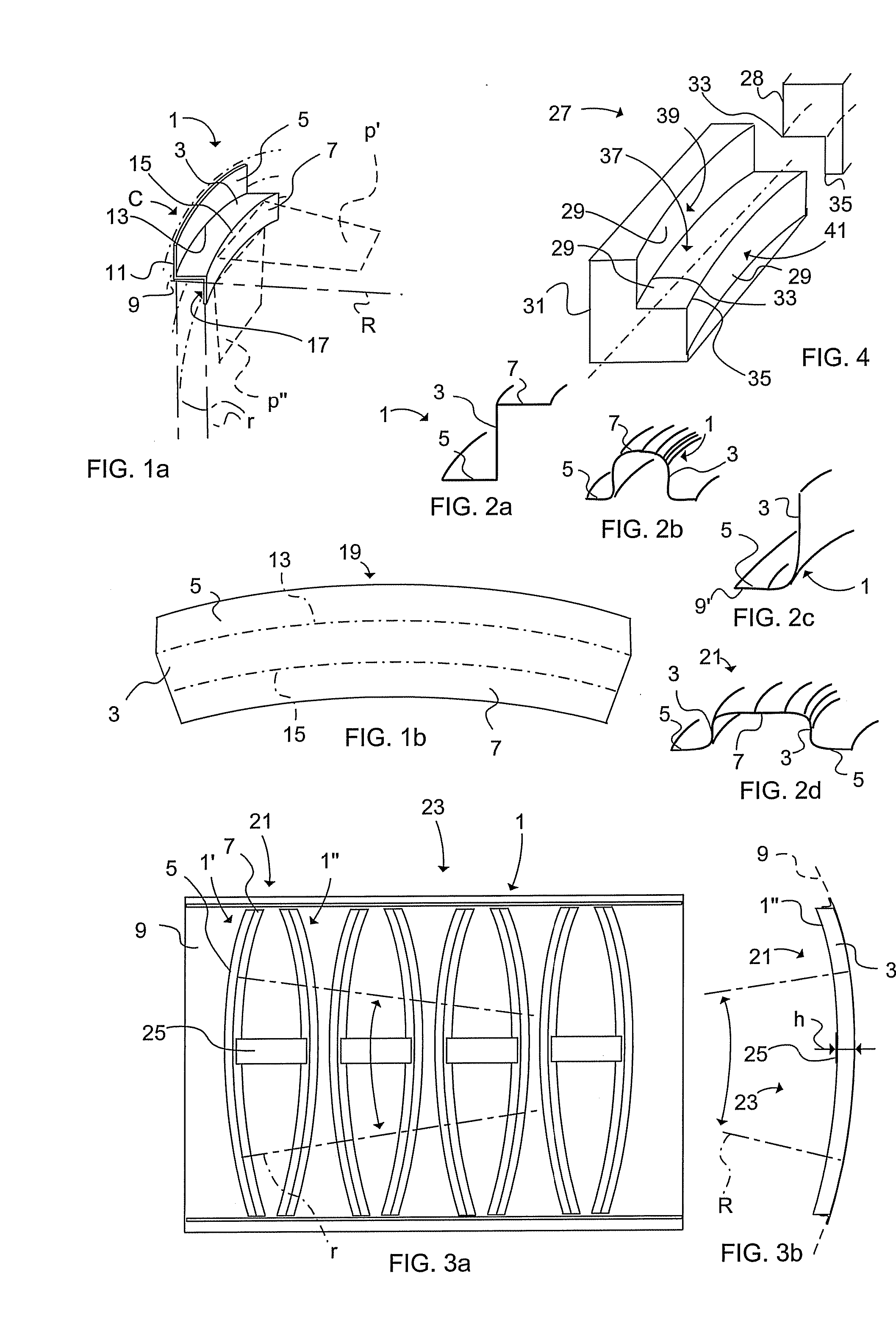
[0052] The Z-profile of the stiffening element 1 in FIG. 1a is shown in FIG. 2a. A Ω-shaped profile of a stiffening element 1 is further shown in FIG. 2b. In FIG. 2c is illustrated a L-profile of a stiffening element 1 according to a Both the web 3 and the first flange 5 (fixation flange) have a curvature corresponding essentially with the curvature of the curved shell inner surface, which according to this embodiment corresponds with a moderate double curved surface 9′, seen in a direction transverse to the surface. FIG. 2d shows schematically a flattened Ω-profile of a stiffening element structure 21 (also shown in FIG. 6a). The moderate double curved surface 9′ comprises surfaces including surfaces with double curvature small enough such that it is possible to wrap a flat blank (lay-up of plastic) on a tool surface without wrinkling the blank. FIG. 2e shows a flat blank 19 provided for a stiffening element 1 with the profile shown in FIG. 2c.

[0053]FIG. 3a illustrates an aircraf...

third embodiment

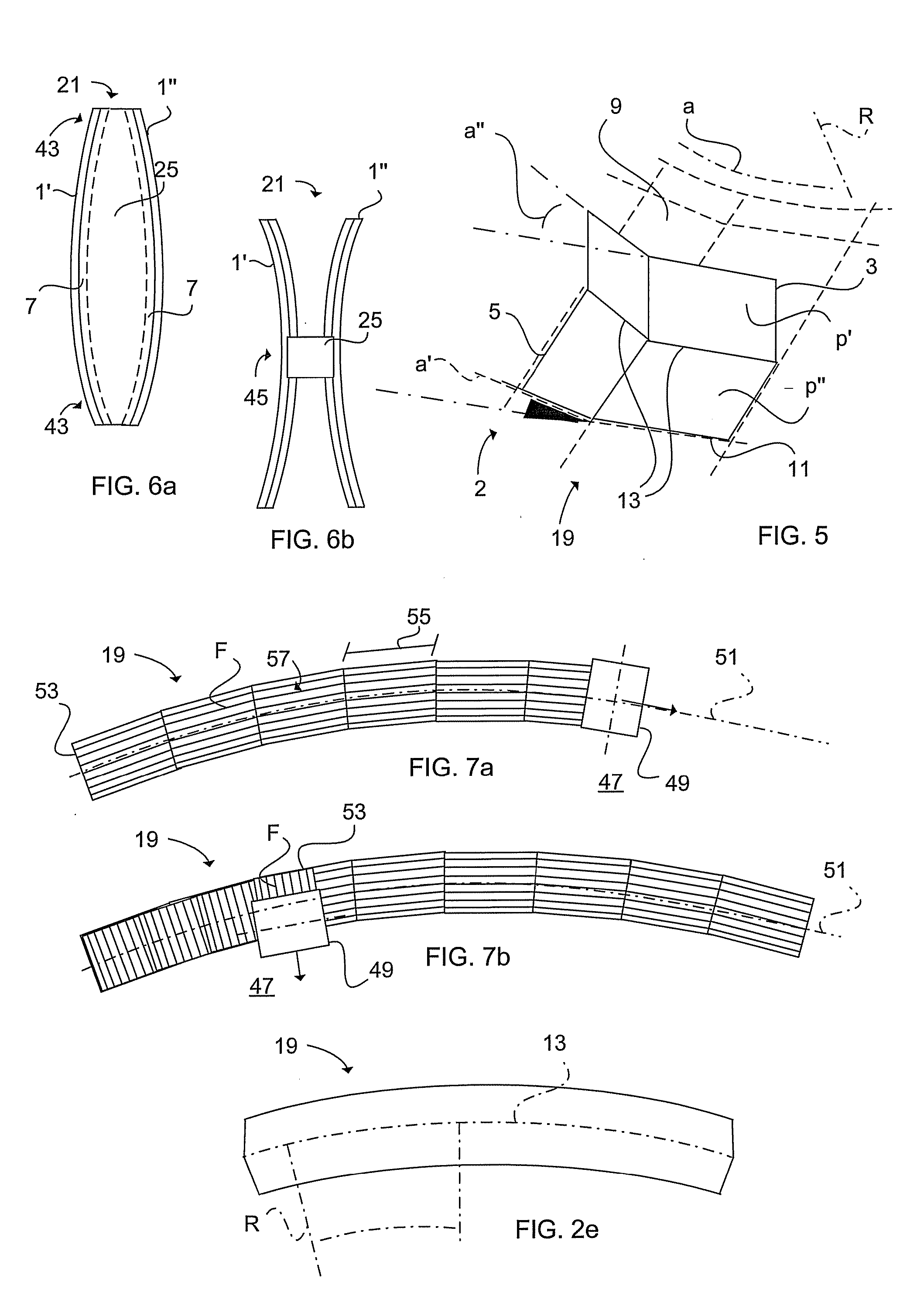
[0057]FIG. 5 illustrates schematically in a perspective view a stiffening element 2 according to the present invention. The stiffening element 2 of this embodiment is manufactured of a blank 19 of plastic without reinforcement fibres. The blank 19 prior folding was square-shaped. The stiffening element 2 comprises a first folding line 13 between a web 3 and a flange 5. The first folding line 13 has a folding direction alteration in a first p′ and a second p″ plane. The first folding line 13 in the first plane p′ has a varying folding direction a′ corresponding essentially with the curved shell surface 9. Furthermore, the first folding line 13 has in the second plane p″ a varying folding direction a″ corresponding with the varying folding direction a′ in the first plane p′. The varying folding direction a corresponds essentially with the mean radius R of the curved shell surface 9 and corresponds essentially with a′ and a″.

[0058]FIG. 6a illustrates a further stiffening element struct...


PUM

PropertyMeasurementUnit
radius of curvatureaaaaaaaaaa
radiusaaaaaaaaaa
curvatureaaaaaaaaaa

Abstract

The present invention relates to a method for manufacturing of a stiffening element (1, 1′, 1″, 2) of composite material, which stiffening element is provided for attachment to a curved shell surface (9), said stiffening element (1, 1′, 1″, 2) comprises a web (3) and at least one flange (5), the outer surface (11) of which has a radius (R) of curvature corresponding with the curvature of said curved shell surface (9) The method comprises the following steps of: providing a substantial flat blank (19) of composite material; and folding said blank (19) along a first folding line (13), the curvature of which is defined by an imaginary three-dimensional intersection line (115) being derived from the radius (R) of curvature of the curved shell surface (9).

Description

FIELD OF THE INVENTION [0001] The present invention relates to a method for manufacturing of a stiffening element of plastic according to the pre-characterising part of claim 1, and to a stiffening element of plastic according to the pre-characterising part of claim 11, and also to a stiffening element structure and to a curved shell panel and a method of manufacturing thereof according to the preamble of claim 14, 15, 17 respectively. The present invention relates, but not limited, to aircraft industry. BACKGROUND OF THE INVENTION [0002] Methods of manufacture of composite materials using “prepreg” material (layer of fibre material previously impregnated with resin) exist today. When manufacturing of stiffening elements, such as aircraft ribs, frames etc., the composite material may have a curvature following a curved shell surface of a fuselage. It is today time-consuming to form an aircraft rib comprising a web and flanges of composite material. Manual work for application of pre...

Claims


Application Information

Patent Timeline
Patent Type & Authority Applications(United States)
IPC IPC(8): B31C7/00B29D99/00
CPCB29C70/345B29D99/0014B29C70/46B29D99/0003
Inventor RAF, MARTIN
Owner SAAB AB
Why Eureka
Try Eureka