Modular prosthetic implant for upper and lower extremity amputees

a prosthetic implant and module technology, applied in the field of surgical implanted prosthetic devices, can solve the problems of short residual cut bone length, lack of structural contribution of the cut bone to control the movement and function of the prosthesis, and lack of strength contribution from non-altered muscles

Inactive Publication Date: 2007-07-12
FAGO JOHN RICHARD +3
View PDF24 Cites 14 Cited by
  • Summary
  • Abstract
  • Description
  • Claims
  • Application Information

AI Technical Summary

Benefits of technology

[0024] The present invention preserves the advantages of prior art prosthetic implant systems. In addition, it provides new advantages not found in currently available prosthesis and implant systems for amputees and overcomes many disadvantages of such currently available systems.

Problems solved by technology

Upper extremity amputees share many of the same functional obstacles that result from a lack of a terminal cut bone structure to transfer force from the residual limb to the external prosthesis, as well as length issues that are the result of disarticulation.
Principal among these are functional limitations imposed by surgical necessities that require a short residual cut bone length, a lack of strength contribution from not otherwise utilized muscles, and a lack of structural contribution from the cut bone to control the movement and function of the prosthesis.

Method used


Image

  • Modular prosthetic implant for upper and lower extremity amputees
  • Modular prosthetic implant for upper and lower extremity amputees
  • Modular prosthetic implant for upper and lower extremity amputees

Examples


Embodiment Construction

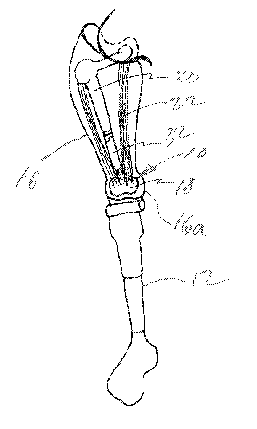
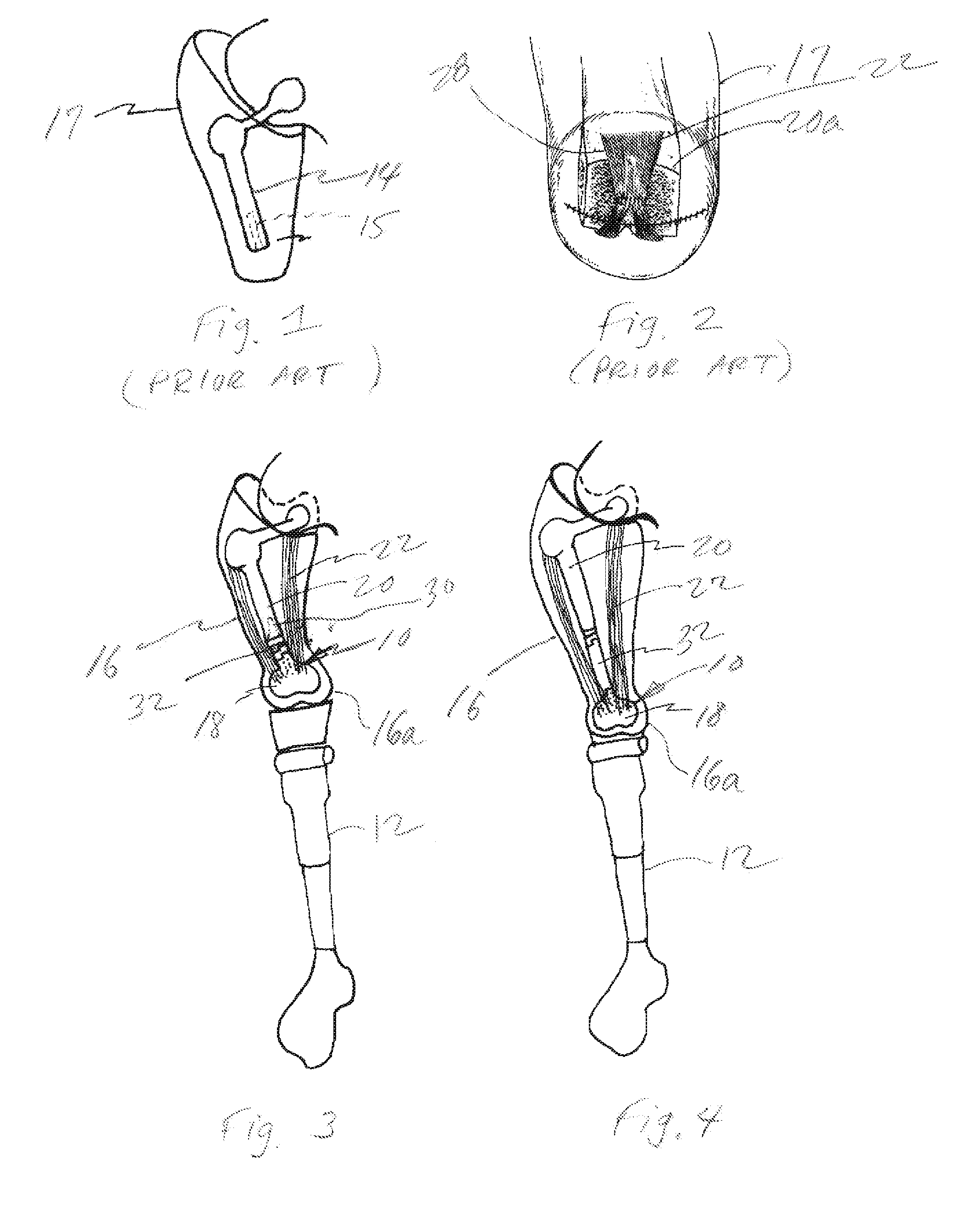
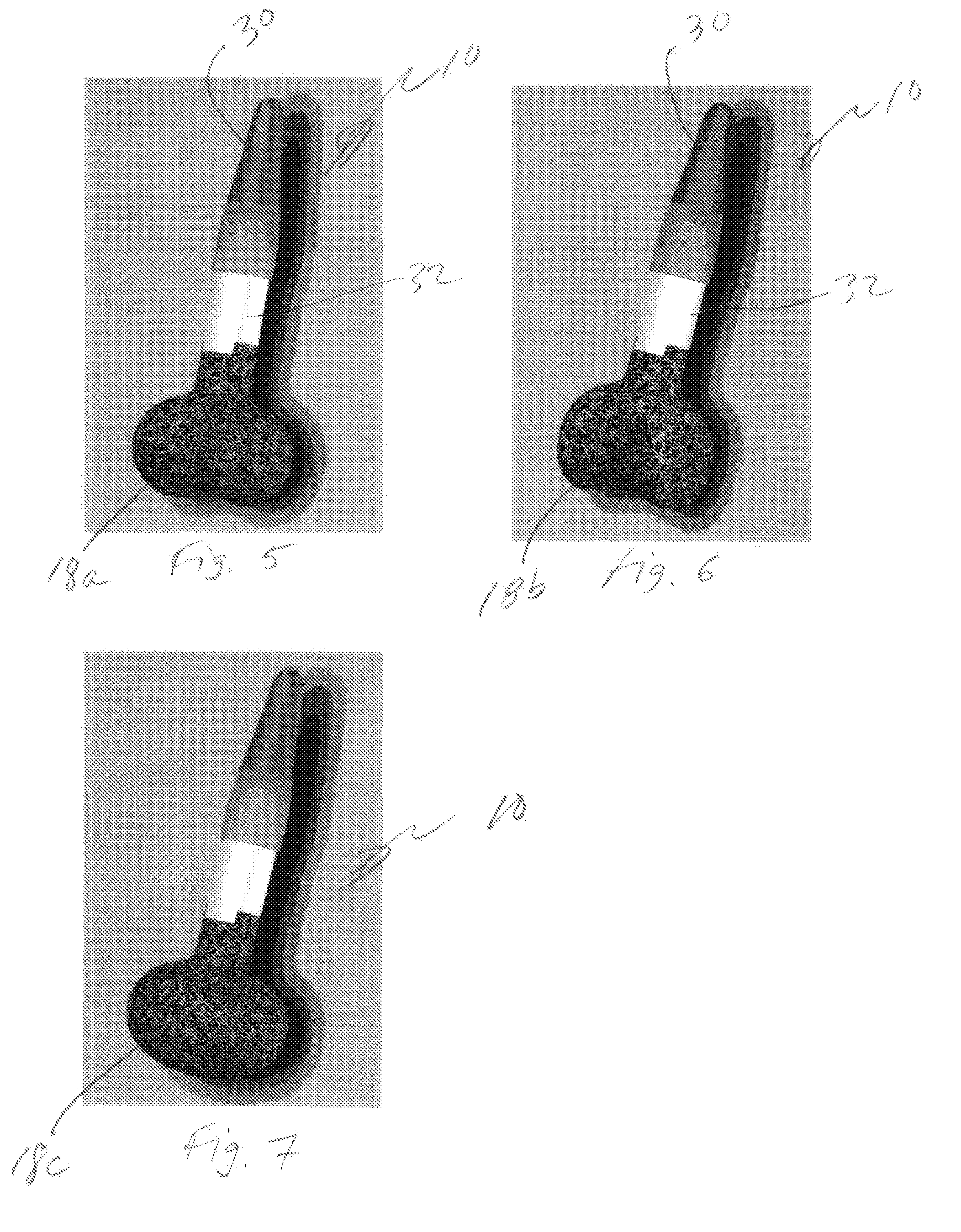
[0053] In accordance with the present invention, first referring to FIGS. 1-4, a new modular implant 10 and method for installing the same into a patient is provided for interfacing with an external prosthesis 12, such as that show in FIG. 8. The present invention provides a way to give back to cut bone trans-femural AK amputees the means to distally transfer mid-stride body weight that was lost at the time of amputation of their natural leg. While a cut end-bone 14 cannot directly bear weight, the novel surgically implanted prosthetic of the present invention create a lengthened residual limb 16 in accordance with the present invention and a condyle-like prosthetic platform, generally referred to as 18, for direct skeletal weight bearing. This represents a fundamental change and dynamic improvement in the connection between the residual limb 16 and the external prosthetic leg 12. A major secondary benefit is the opportunity to prosthetically extend the length of the residual femur ...


PUM


Abstract

The invention is generally directed to the novel and unique modular implant that provides an improved surface for interfacing with an external prosthesis. The implant includes a stem, an optional extension member connected to the stem, a prosthetic condyle, or in the case of application to other levels of cut bone amputations, a location-specific terminal shape, connected to the extension member. The stem is inserted directly into the canal of the bone and tissue, including muscle, is attached directly to the prosthetic and the stem is inserted directly into the canal of the bone. The simulated anatomically correct condyle better distributes the load of the patient's weight and avoids twisting thereby relieving pain to improve the functional connection between the residual limb and an external prosthesis in all levels of upper and lower extremity amputations. The surgically implanted internal prosthetic simplifies and lowers the cost of rehabilitation and results in an improvement in the function of all existing external prosthetic components and systems.

Description

CROSS REFERENCE TO RELATED APPLICATION [0001] This application claims the benefit of the Provisional Application No. 60 / 758,448, filed Jan. 12, 2006.BACKGROUND OF THE INVENTION [0002] The present invention relates to a surgically implanted prosthetic device for the distal end of the cut bone for amputees that can be implanted to improve functional rehabilitation for all levels of lower and upper extremity amputation. More particularly, it relates to an implant designed to be application specific that provides increased surface area and more anatomic geometry for external loading, that resists rotation of an externally fit prosthesis, and a method for soft tissue fixation to improve amputee function. [0003] There are approximately 180,000 lower limb amputations performed annually, of which approximately 45,000 are above the knee, also known as “AK” as reported by the Amputee Coalition of America—National Limb Loss Information Center in 2002 at http: / / www.amputeecoalition.org / fact she...

Claims


Application Information

Patent Timeline
Patent Type & Authority Applications(United States)
IPC IPC(8): A61F2/30A61F2/74
CPCA61F2/2814A61F2310/00011A61F2/3859A61F2/54A61F2/60A61F2002/30332A61F2002/30551A61F2002/30604A61F2002/30606A61F2002/30616A61F2002/30878A61F2002/4631A61F2002/607A61F2002/6614A61F2002/7887A61F2220/0033A61F2/30749A61F2002/3055
Inventor FAGO, JOHN RICHARDFAGO, JULIE PATTERSONGREENWALD, RICHARD M.MAYOR, MICHAEL B.
Owner FAGO JOHN RICHARD
Why Eureka
Try Eureka