Dual thermodynamic cycle cryogenically fueled systems

a technology of thermodynamic cycle and cryogenic fluid, which is applied in the direction of mechanical equipment, machines/engines, lighting and heating apparatus, etc., can solve the problems of increasing the expansion process, the inefficient production of mechanical power from the phase change of the cryogenic fluid to the expanding gas, and the inability to use the phase change in the cryogenic fluid to achieve the expansion process. , to achieve the effect of reducing the expansion process, and increasing the energy of the second gas

Inactive Publication Date: 2007-07-19
MEV TECH
View PDF10 Cites 70 Cited by
  • Summary
  • Abstract
  • Description
  • Claims
  • Application Information

AI Technical Summary

Problems solved by technology

Although liquid nitrogen powered engines useful for example in an automobile have been studied in the past, there have been problems with such engines, including implementing a quasi-isothermal expander and a frost-free liquid nitrogen heat exchange system.
There are several problems with using cryogenic fluids, including that cryogenic fluids need very effective thermal insulation, have significant problems with ice condensation within an engine from the cold temperature fluids used, and are extremely inefficient for the production of mechanical power from the phase change of the cryogenic fluid to an expanding gas.
The extremely inefficient production of mechanical power from the phase change of the cryogenic fluid to an expanding gas is the biggest problem with existing technology.
Using phase change in a cryogenic fluid has additional serious problems.
Conventional systems merely dump the heat from the cold cryogenic fluid at atmospheric ambient temperatures, and do not fully utilize the thermodynamic possibilities available from the cryogenic fluid.
Some systems use nitrogen gas to preheat the cryogenic fluid before it enters the heat exchanger, but this only provides a minor improvement in the overall efficiency of the energy conversion in the engine.
Conventional thermal power engines utilizing cryogenic fluids suffer from a serious limitation, which is low efficiency in the energy conversion.

Method used


Image

  • Dual thermodynamic cycle cryogenically fueled systems
  • Dual thermodynamic cycle cryogenically fueled systems
  • Dual thermodynamic cycle cryogenically fueled systems

Examples


Embodiment Construction

[0028] Embodiments of the invention can be constructed from commercially available components. In all of the embodiments disclosed below, different materials could be used for the chambers and reservoirs, including but not exclusively including: various plastics, rubbers, resins, ceramics, and metals. In all of the embodiments disclosed below, different materials could be used for the piping, including but not exclusively including: various plastics, rubbers, resins, ceramics, metals, or other equivalent manmade materials. The heat exchanger could be a low-temperature heat exchanger, a mid-temperature heat exchanger, a high-temperature heat exchanger, or a combination of different types of heat exchangers.

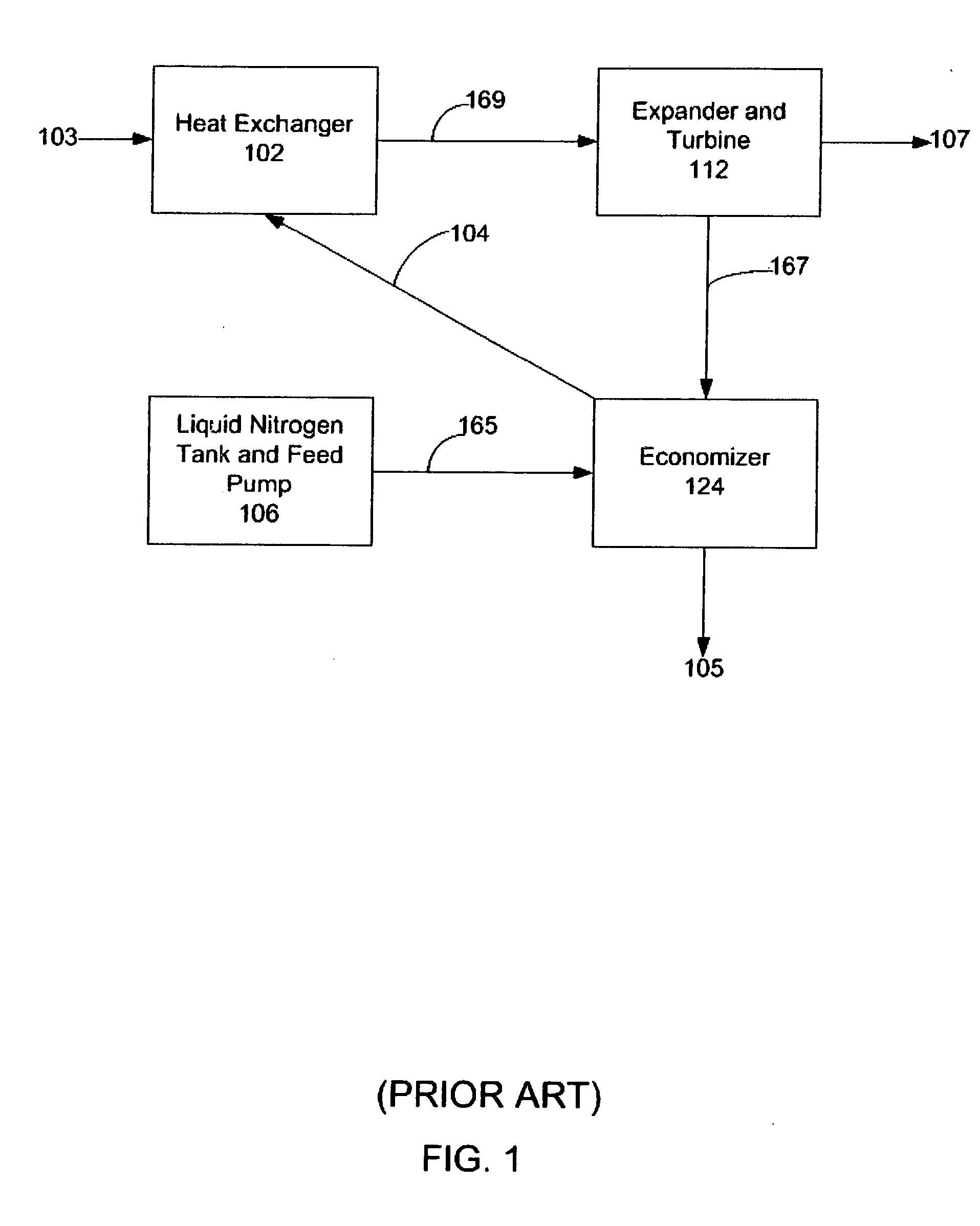
[0029]FIG. 1 illustrates a block diagram of a conventional open Rankine cycle liquid nitrogen engine that has been extensively studied at the University of Washington. As shown, the engine has a heat source supplying heat 103 to a heat exchanger 102 that is connected with a pipe 1...


PUM


Abstract

Systems and methods for converting thermal energy, such as solar energy, from a localized thermal energy source to another form of energy or work comprise dual thermodynamic cycle systems that utilize the liquid-to-gas phase transitions of a cryogenic fluid such as liquid nitrogen and a working fluid such as sulfur hexafluoride to drive prime movers. Heat transfer between the fluids as they undergo the phase transitions is used to increase the energy in the system and its work output, and improve system efficiency.

Description

CROSS-REFERENCE TO RELATED APPLICATIONS [0001] This application claims the benefit of U.S. provisional patent Application No. 60 / 735,056, filed Nov. 8, 2005, and U.S. provisional patent Application No. 60 / 737,682, filed Nov. 17, 2005, the disclosures of which are hereby incorporated by reference herein.TECHNICAL FIELD [0002] The invention relates generally to methods and apparatus utilizing cryogenic fluids, and more particularly to methods and apparatus for utilizing cryogenic fluids for thermal energy conversion and to operate prime movers. BACKGROUND OF THE INVENTION [0003] Systems utilizing cryogenic fluids to operate prime movers (e.g., engines, turbines, motors, pumps, generators, and equivalents) to produce various forms of energy have been investigated as environmentally clean sources of energy. A cryogenic automobile is a zero-emission vehicle, and one example of such a clean energy system. It operates on the thermodynamic potential between the ambient atmosphere and a rese...

Claims


Application Information

Patent Timeline
Patent Type & Authority Applications(United States)
IPC IPC(8): F01K25/08F01K3/00F24S10/95
CPCF01K23/00F01K23/18F01K25/085Y02E10/46F03G6/00F03G6/068F01K25/10
Inventor STRATHMAN, MICHAEL D.
Owner MEV TECH
Why Eureka
Try Eureka