Isolated fuel delivery system

a fuel delivery system and fuel technology, applied in the direction of threaded fasteners, screws, machines/engines, etc., can solve problems such as vibrations and nois

Inactive Publication Date: 2007-07-19
GM GLOBAL TECH OPERATIONS LLC
View PDF11 Cites 70 Cited by
  • Summary
  • Abstract
  • Description
  • Claims
  • Application Information

AI Technical Summary

Benefits of technology

[0005] Accordingly, the isolated fuel delivery system of the present invention reduces the transmission of noise producing, high frequency vibrations from the fuel injector and fuel rail to the engine.
[0007] Additionally, a first and a second of the at least one clamping members may be provided, with each having a first and second edge. The first and second clamping members may have a lip portion at least partially disposed about at least one of the first and second edges. The lip portion is spaced from the fuel rail by a predetermined amount and is operable to locate and limit the movement of the isolating member with respect to the first and second clamping members. The clamping member may permit the fuel rail to move with respect to the clamping member to enable changes in orientation of the fuel rail and the fuel injector. The clamping member may be integral with one of the cylinder head and the intake manifold and may extend substantially the length of the fuel rail.
[0010] Also provided is an isolated fuel delivery system for an internal combustion engine having a fuel rail operable to deliver fuel to at least one fuel injector. The fuel rail also includes at least one mounting boss portion. The mounting boss portion defines a bore that is dimensioned to receive a fastener. The fastener is operable to removably attach the fuel rail to the engine. Also provided is a plurality of isolating members, each disposed at a respective opposite axial end of the mounting boss and operable to damp the vibrations of the fuel rail.

Problems solved by technology

The sequential energization of the fuel injectors may operate to induce pressure pulsations within the fuel rail, which may produce noise-emitting vibrations.

Method used


Image

  • Isolated fuel delivery system
  • Isolated fuel delivery system
  • Isolated fuel delivery system

Examples


Embodiment Construction

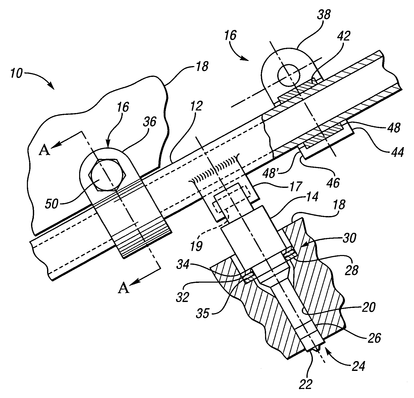
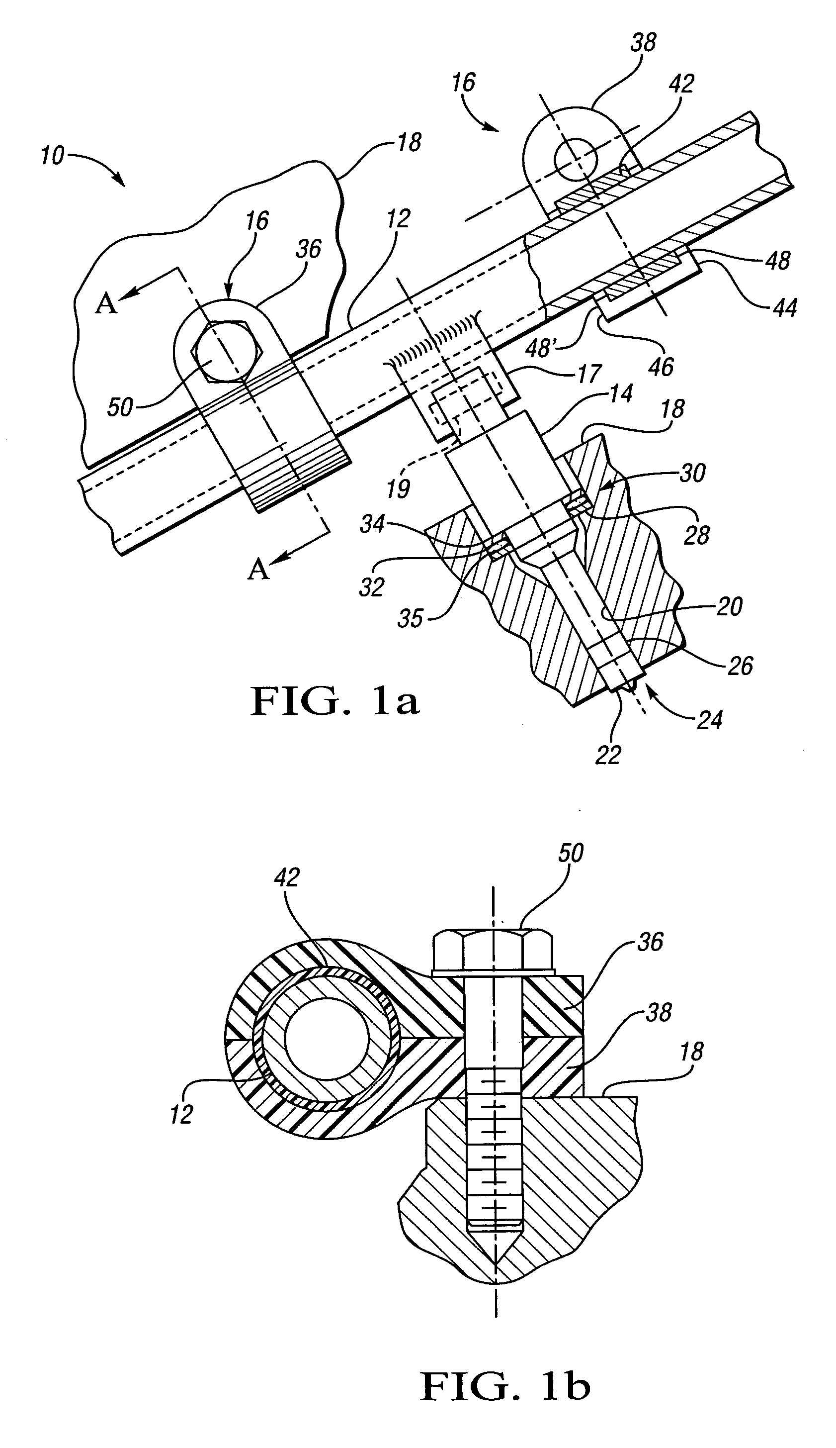
[0021] Referring to the drawings wherein like reference numbers represent like components throughout the several figures, there is shown in FIG. 1a an isolated fuel delivery system 10 having a fuel rail 12, a fuel injector 14, and a clamp assembly 16. The fuel rail 12 operates as a conduit to communicate pressurized fuel to the fuel injector 14. Although only one fuel injector 14 is shown in FIG. 1a, those skilled in the art will recognize that the fuel rail 12 may operate as a manifold to provide multiple fuel injectors 14 with pressurized fuel. A fuel injector boss 17 is operable to retain one end of the fuel injector 14 with respect to the fuel rail 12, while another end of the fuel injector 14 is disposed within a cylinder head 18. The fuel injector 14 has an injector seal 19, shown in dashed lines, to contain pressurized fuel within the fuel rail 12. The cylinder head 18 defines an injector bore 20, which is dimensioned such that the fuel injector tip 22 can pass though the hea...


PUM


Abstract

An isolated fuel delivery system for an internal combustion engine includes a fuel rail with a clamping method operable to retain an isolating member with respect to the fuel rail. The isolating member operates to isolate the vibratory motion of the fuel delivery system form the attachment point or points. The attachment point is typically a cylinder head of the internal combustion engine. Additionally, an isolating ring assembly is provided having a first and second stiffening member with an isolating ring member disposed therebetween. The isolating ring assembly is disposed between a fuel injector of the isolated fuel delivery system and the cylinder head. The isolating ring member operates to isolate the vibratory motion of the fuel injector from the internal combustion engine.

Description

TECHNICAL FIELD [0001] The present invention relates to fuel delivery systems for internal combustion engines. BACKGROUND OF THE INVENTION [0002] Fuel delivery systems for internal combustion engines are available in many different varieties. One of the more common of which is the port fuel injection system. The port fuel injection system utilizes a plurality of fuel injectors each of which delivers a predetermined amount of fuel to the inlet port of an associated combustion chamber. In such systems, the fuel injectors are mounted in sockets or injector bosses of a manifold or fuel rail, which operates to communicate fuel to each of the injectors. [0003] Recent advances in fuel delivery and combustion research has allowed direct injection, or DI, fuel delivery systems to increase in popularity. The DI fuel delivery system provides a fuel injector within the cylinder head of the internal combustion engine. The DI fuel injector operates to inject a predetermined amount of fuel directl...

Claims


Application Information

Patent Timeline
Patent Type & Authority Applications(United States)
IPC IPC(8): F02M69/46F02M61/14
CPCF02M55/025F02M55/04F02M2200/9015F02M2200/306F02M61/14
Inventor BEARDMORE, JOHN M.HAMILTON, MATTHEW TIMOTHY
Owner GM GLOBAL TECH OPERATIONS LLC
Why Eureka
Try Eureka