Velocity-changing apparatus for web
a technology of velocity-changing apparatus and web, which is applied in the field of velocity-changing apparatus for web, can solve the problems slowing down the production line, and requiring more processing time for processing of web by ultrasonic welding, and achieves the effect of reducing production efficiency and more processing tim
- Summary
- Abstract
- Description
- Claims
- Application Information
AI Technical Summary
Benefits of technology
Problems solved by technology
Method used
Image
Examples
first embodiment
[0036] Embodiments of the present invention will now be described with reference to the drawings.
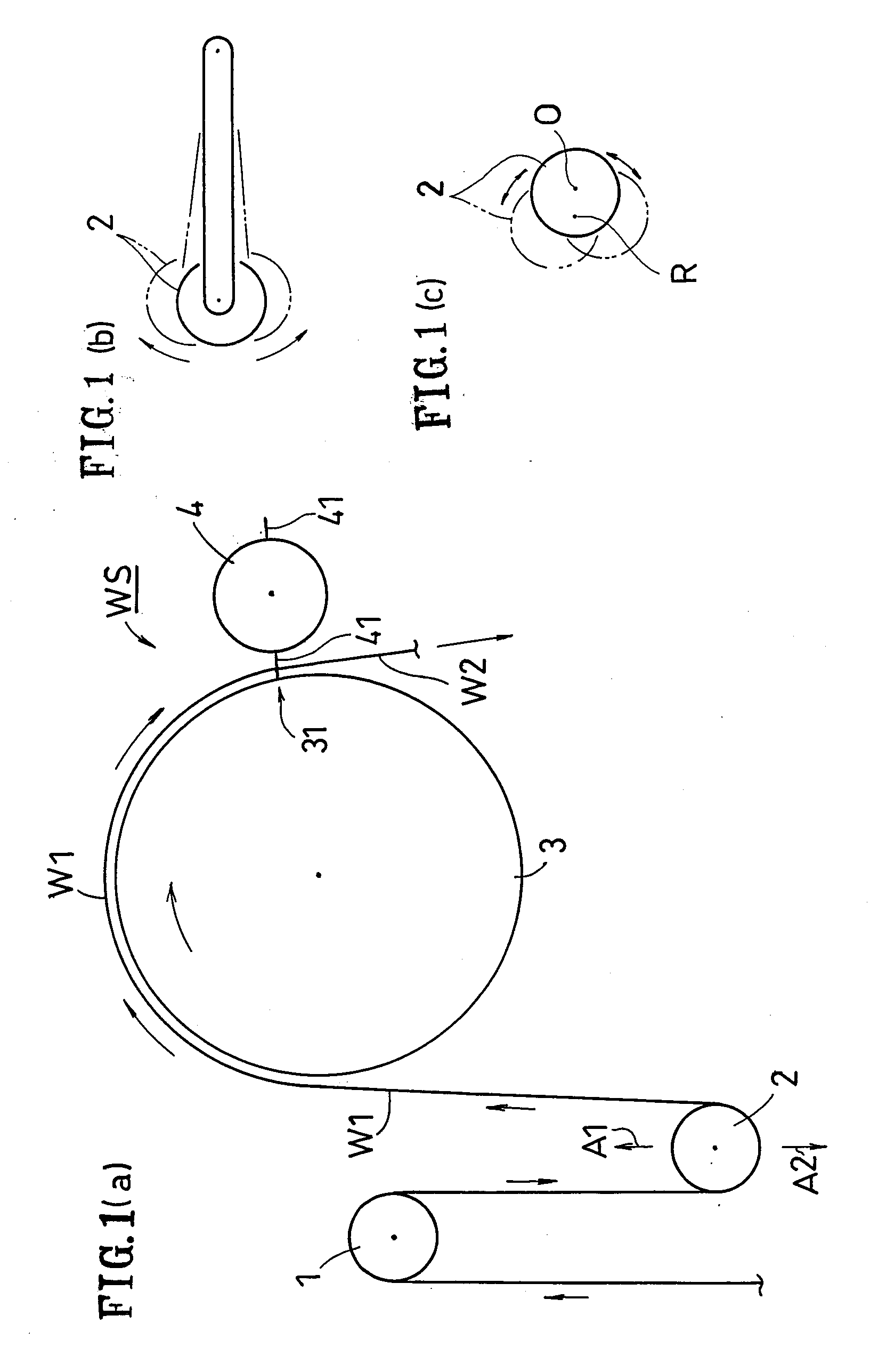
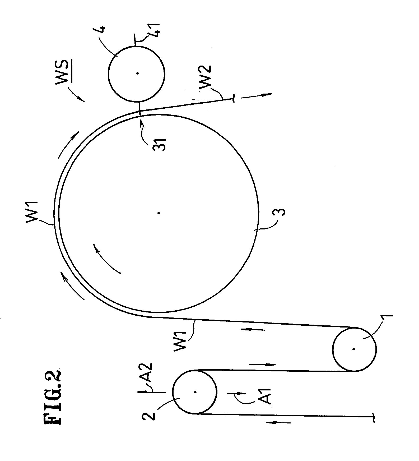
[0037]FIG. 1 shows the first embodiment, which includes a velocity-changing apparatus WS for web.
[0038] According to this embodiment, the velocity-changing apparatus WS includes a movable roller 2 (an example of movable member), a work drum 3 and a cutter roller 4. A fixed roller 1 may be located upstream of the movable roller 2. A continuous web W1 is fed successively to the work drum 3 from the movable roller 2, which is located upstream of the work drum 3. On the outer circumferential surface of the cutter roller 4, two blades 41 are provided. One or more blade rests (beds) for receiving the blades 41 may be provided on the work drum 3.
[0039] The work drum 3 can rotate while changing periodically its circumferential velocity V(θ) (peripheral velocity). Thus, in a case where a processing device is provided on the work drum 3, the work drum 3 enables the continuous web W1 to move at ...
second embodiment
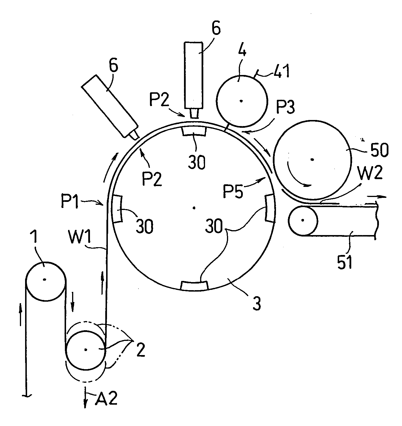
[0055] The velocity-changing apparatus of the present invention may include a processing device. The processing device is capable of carrying out steps of cutting, forming holes, sealing, attaching or applying something, or the like. For example, in a case of welding or sealing the continuous web W1, ultrasonic welding means or heat sealing means may be employed thereto. Hereinafter, the second embodiment, in which ultrasonic welding means is used, will be described with reference to FIGS. 3(a), 3(b).
[0056] At least one main body of the processing device 6 is located around the work drum 3. As shown in FIGS. 3(a), 3(b), the work drum 3 may include a plurality of anvils (receiving beds) 30. In addition, the work drum 3 may hold the continuous web W1 by suction or by mechanical means at the anvils 30 and / or a portion other than the anvils 30.
[0057] As shown in FIG. 3(a), the continuous web W1 is received by the work drum 3 at a receiving position P1 of the work drum 3 and is process...
third embodiment
[0067]FIG. 4 shows the third embodiment.
[0068] In this embodiment, as shown in FIG. 4, a adjustment drum having a plurality of pads 55 is employed as the receiving device 50, in which drum the interval between the pads is adjusted by rotating the pads 55 while changing their circumferential velocity. For example, the circumferential velocity of the pad 55 may reach its maximum at the hand-over position P5 and then be decreased to a velocity commensurate with the velocity of the conveyor 51 when the cut-off web W2 is transferred to the conveyor 51. A structure as disclosed in Japanese Laid-Open Patent Publication No. 2002-345889 may be employed for the adjustment drum.
PUM
| Property | Measurement | Unit |
|---|---|---|
| velocity | aaaaa | aaaaa |
| transport velocity | aaaaa | aaaaa |
| circumferential velocity | aaaaa | aaaaa |
Abstract
Description
Claims
Application Information
 - R&D
- Intellectual Property
- Life Sciences
- Materials
- Tech Scout
- Unparalleled Data Quality
- Higher Quality Content
- 60% Fewer Hallucinations
Browse by: Latest US Patents, China's latest patents, Technical Efficacy Thesaurus, Application Domain, Technology Topic, Popular Technical Reports.
© 2025 PatSnap. All rights reserved.Legal|Privacy policy|Modern Slavery Act Transparency Statement|Sitemap|About US| Contact US: help@patsnap.com


