Microchannel heat sink

a heat sink and microchannel technology, applied in the field of heat sinks, can solve the problems of heat generated by electrical components such as integrated circuits, and must be dissipated or cooled, and achieve the effect of increasing efficiency

Active Publication Date: 2007-07-19
COOLIT SYSTEMS INC
View PDF10 Cites 41 Cited by
  • Summary
  • Abstract
  • Description
  • Claims
  • Application Information

AI Technical Summary

Benefits of technology

[0006] The present invention provides a heat sink and method of transferring heat from a heat source to a coolant fluid by flowing coolant into inlet manifold channels extending into a inlet edge of a manifold where the flow is forced downward into parallel and spaced micro-channels extending across the manifold channels and re-directing the coolant up into and out of outlet manifold channels extending into an outlet edge of the manifold and interleaved with the inlet manifold channels. The increased efficiency is o

Problems solved by technology

Electrical components, such as integrated circuits, generate heat that must b

Method used


Image

  • Microchannel heat sink
  • Microchannel heat sink
  • Microchannel heat sink

Examples


Embodiment Construction

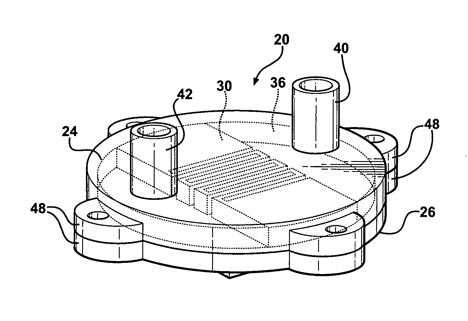
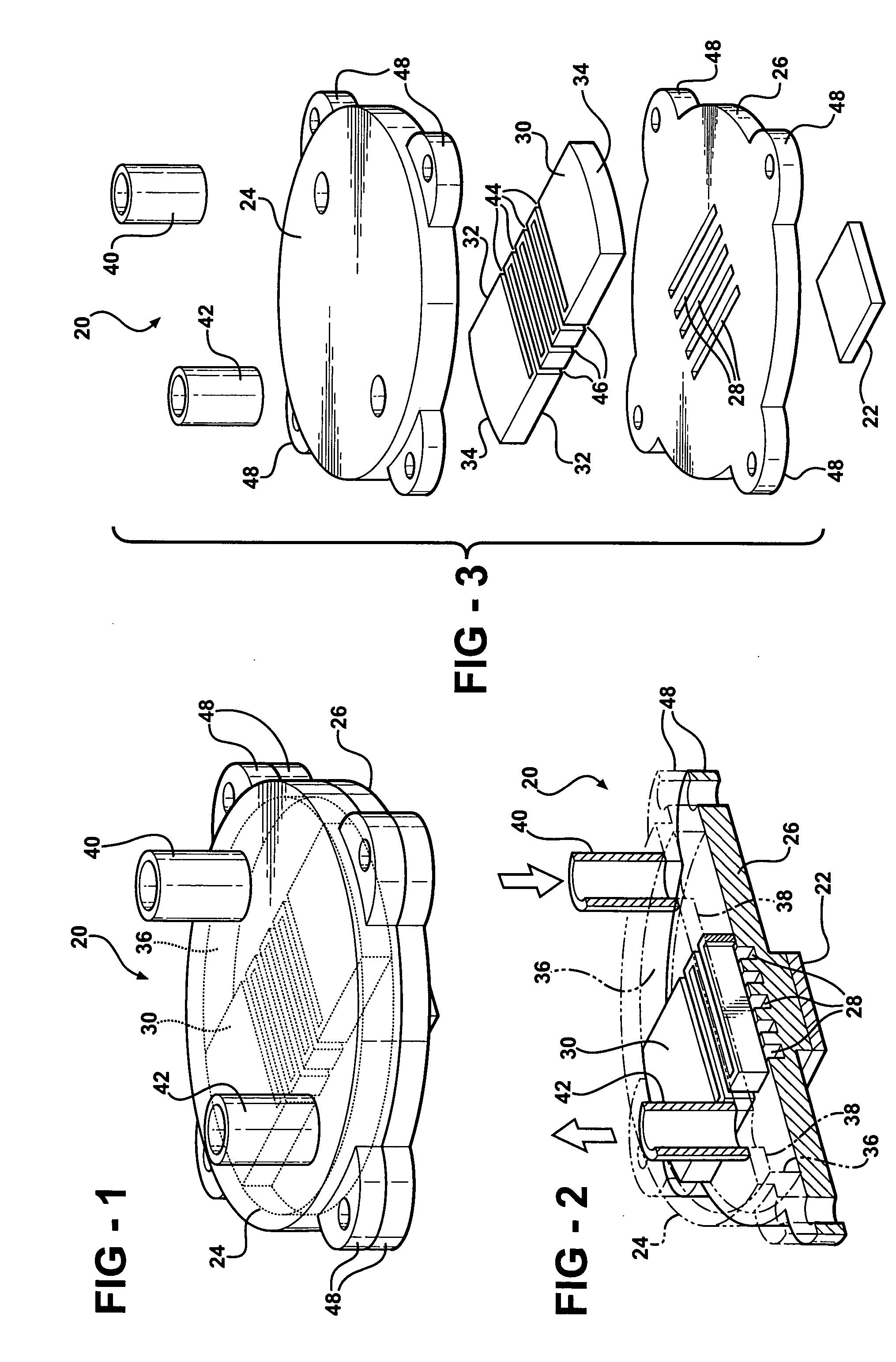
[0015] Referring to the Figures, wherein like numerals indicate corresponding parts throughout the several views, a heat sink 20 is shown generally for transferring heat from a heat source 22 or electronic component to a coolant fluid.

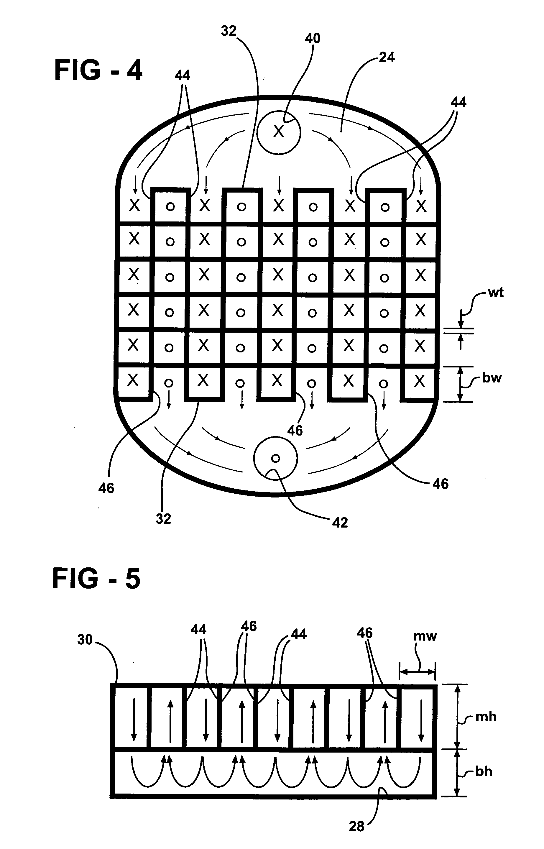
[0016] The heat sink 20 is defined by a housing including a lid 24 and a base 26, the base 26 being a flat cold plate having a top surface and a bottom surface and parallel micro-channels 28 all extending the same distance and each having a base-width bw and a base-height bh into the top surface of the base.

[0017] A manifold plate 30, having a top face and a bottom face to define a manifold-thickness mt, is disposed with the bottom face overlying the micro-channels 28 and having spaced edges 32 extending between opposite ends 34. The lid 24 has a periphery engaging the base and an interior shoulder 36 engaging the ends 34 of the manifold plate 30 to define a recessed surface 38 within the periphery and in engagement with the top face of the manifold ...


PUM


Abstract

The invention provides a heat sink for flowing coolant into inlet manifold channels extending into a inlet edge of a manifold where the flow is forced downward into parallel and spaced micro-channels extending across the manifold channels and re-directing the coolant up into and out of outlet manifold channels extending into an outlet edge of the manifold and interleaved with the inlet manifold channels, and by maintaining a base-width of the micro-channels in the range of forty microns to one hundred microns, maintaining a base-height of the micro-channels in the range of two hundred microns to four hundred microns, maintaining a manifold-height through of the manifold channels in the range of one thousand microns to three thousand microns, and maintaining a manifold-width of the manifold channels in the range of three hundred and fifty microns to one thousand microns.

Description

BACKGROUND OF THE INVENTION [0001] 1. Field of the Invention [0002] The subject invention provides heat sink for transferring heat from a heat source to a coolant fluid and a method of operation. [0003] 2. Description of the Prior Art [0004] Electrical components, such as integrated circuits, generate heat that must be dissipated or cooled because heat negatively impacts electrical components. Heat sinks have been employed to dissipate heat and include successive tiers of overlapping channels above a cold plate or base against which the electronic heat component is disposed. Such a heat sink is disclosed in U.S. Pat. No. 5,388,635 to Gruber et al. Typically a flat cold plate or base presents parallel passages or channels all extending the same distance in the cold plate and a manifold plate overlies the cold plate. The electronic component is mounted on the opposite face of the cold plate and coolant flow through the passages to extract heat from the electronic component. [0005] It ...

Claims


Application Information

Patent Timeline
IPC IPC(8): H05K7/20
CPCF28F3/12F28F9/026F28F13/06H01L23/473H01L2924/0002H01L2924/00
Inventor BHATTI, MOHINDER SINGHPARISI, MARK JOSEPHHAYES, ANDREW R.
Owner COOLIT SYSTEMS INC
Why Eureka
Try Eureka