Lockwireless coupling assembly

a technology of coupling assembly and lock wire, which is applied in the direction of pipe-joints, mechanical devices, joints with sealing surfaces, etc., can solve the problems of loose connection, unsatisfactory means of securing the joint, and loosening of the lock wire, so as to prevent leakage across the seal, facilitate visual confirmation, and prevent leakage

Inactive Publication Date: 2007-07-19
SHUR LOK CORP
View PDF28 Cites 25 Cited by
  • Summary
  • Abstract
  • Description
  • Claims
  • Application Information

AI Technical Summary

Benefits of technology

[0009] The nut member internally receives the first engagement end of the ferrule member, the second engagement end of the connector member, and the rotational locking means of the ferrule member. The nut member comprises fastening means, such as threads, which are adapted to engage the fastening means of the connector member. When the nut member is fully made up with the connector member, the sealing surface of the ferrule member is brought into sealing engagement with the sealing surface of the connector member to prevent leakage across the seal. The nut member may further comprise cantilever members which provide a platform for locating locking means for engaging the serrations of the ferrule member. Between adjacent cantilever members are openings which may facilitate visual confirmation that the serrations of the ferrule member are engaged within the nut member thereby resisting the rotation of the nut member.
[0010] The locking means of the nut member may comprise at least one inwardly protruding lock engagement member disposed on a cantilever member, wherein the lock engagement member is adapted to engage the serrations of the ferrule member when the nut member is made up in full engagement with the connector member and the sealing surface of the ferrule member is brought into sealing engagement with the sealing surface of the connector member to prevent leakage across the seal.

Problems solved by technology

However, it is known that various phenomena such as vibration, flexing, or other cyclical or dynamic loading can cause such couplings to work loose potentially resulting in fluid release.
The loosening of the connection can be a particular problem for pneumatic and hydraulic connectors, which are not only subjected to external vibrations and stresses, but also subjected to internal pressure stresses from the fluid that is being conducted through the sealed joint.
However, fluid coupling joints are frequently located in areas where vision can be obscured, and the assembling of the joints must be made out of the direct vision of the worker.
In such events, lock wiring is an unsatisfactory means of securing the joint against subsequent loosening.
In addition, the lock wiring process can be time consuming.
Moreover, the lock wired connection can cause damage to equipment, and injury to personnel because of the twisted wire ends which easily snag on fabric, equipment, and skin.
While various other lockwireless coupling assemblies have been disclosed, many of these require multiple or complicated parts to achieve the locking of the connection.
The increased length of the connector results in increased weight of the coupling, and can also complicate the installation where space is limited.

Method used


Image

  • Lockwireless coupling assembly
  • Lockwireless coupling assembly
  • Lockwireless coupling assembly

Examples


Embodiment Construction

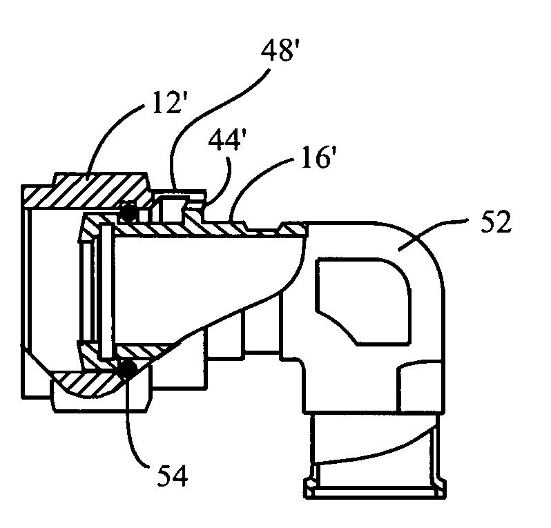
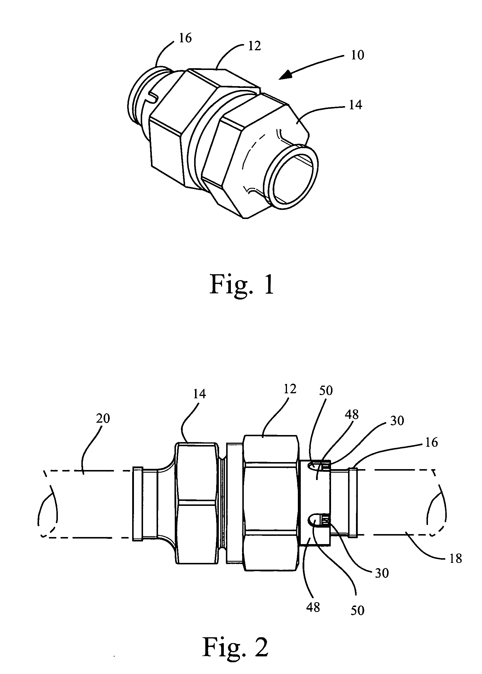
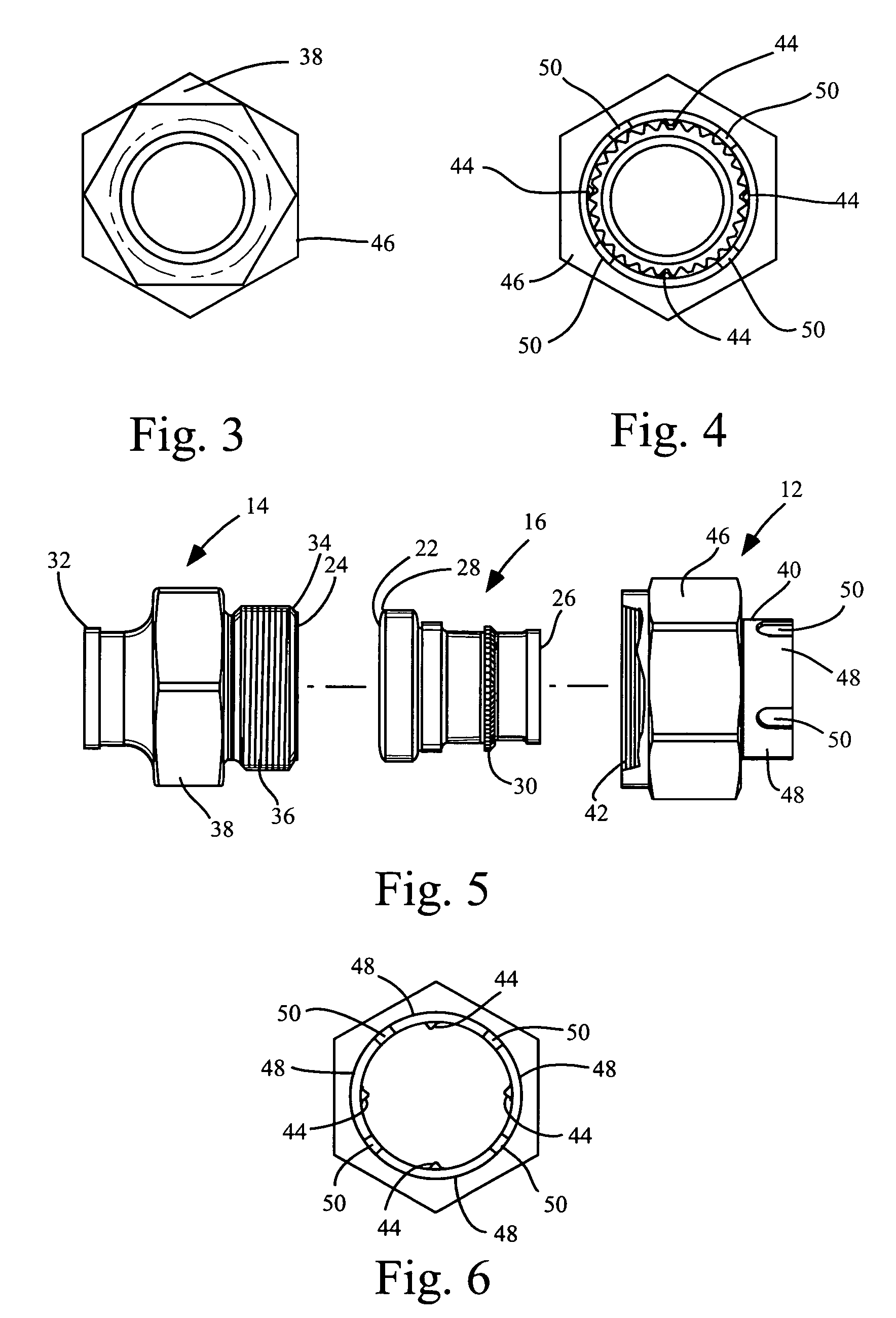
[0020]FIG. 1 shows the basic components of an embodiment of the disclosed coupling 10 in an assembled configuration, but shown without the connecting fluid conduits. The coupling 10 comprises a nut member 12, a connector member 14, and a ferrule member 16 which is only partially shown in FIG. 1. As shown in FIG. 2, the coupling 10 is utilized to connect fluid bearing conduit members which may be disposed in an opposite facing configuration as shown in FIG. 2, that is, where the fluid bearing conduit members are in axial alignment. An alternative embodiment, as shown in FIG. 7 through 9 may be utilized in which the fluid bearing conduit members are in a ninety-degree configuration.

[0021] First fluid conduit 18 is connected by the coupling 10 to a second fluid conduit 20. The second fluid conduit 20 is attached and sealed to connector member 14 by means known in the art, such as by welding, dynamic seal beam, flaring, flareless connection, crimping, swaging, lock ring, or other means...


PUM


Abstract

A self-locking fluid coupling, utilized to connect two fluid conduits together, does not require the lockwiring of the coupling nut to prevent the rotation of the coupling nut. The locking mechanism comprises a rotational locking means on a ferrule member. The rotational locking means engage one or more inwardly protruding engagement members of the B-nut. The engagement of the rotational locking means of the ferrule with the engagement members of the B-nut creates resistance to circular motion, thereby resisting rotation of the B-nut and eliminating the requirement for lockwire to resist rotation of the B-nut.

Description

CROSS-REFERENCE TO RELATED APPLICATION [0001] U.S. Provisional Application No. 60 / 760,100 for this invention was filed on Jan. 19, 2006 for which the inventor claims domestic priority.BACKGROUND OF THE INVENTION [0002] The present invention is broadly directed to a locking assembly for fastening two fluid-transmitting conduits together and, more particularly, to an improved fluid coupling assembly for providing a compression sealed joint that can maintain its preload characteristics without the utilization of lock wire or other externally applied devices or chemical compositions. [0003] Numerous devices have been utilized to retain the mechanical coupling of fluid-transmitting conduits during use. As is well known, application of stress, vibration, movement, etc. to a coupled connection can cause a loosening and release of a desired seating torque between a pair of fluid-transmitting conduits which have been coupled together. A typical method of connecting two adjacent fluid-transmi...

Claims


Application Information

Patent Timeline
Patent Type & Authority Applications(United States)
IPC IPC(8): F16L25/00
CPCF16L19/005
Inventor PATEL, NILESH
Owner SHUR LOK CORP
Why Eureka
Try Eureka