Tubular electrical machines

Inactive Publication Date: 2007-07-19
GE POWER CONVERSION
View PDF4 Cites 19 Cited by
  • Summary
  • Abstract
  • Description
  • Claims
  • Application Information

AI Technical Summary

Benefits of technology

[0035] If the superconducting coils are formed in the outer member and the armature coils are formed in the inner member then, if the outer member is held stationary, the problem of stray flux escaping the tubular machine can be eliminated because the superconducting coils are held stationary relative to the surroundings of the tubular machine at all times. The cryocooling system and exciter for the superconducting coils would also remain stationary and their construction would thus be much simpler. However, the main disadvantages of a tubular machine constructed in this manner are that the main power connection for the armature coils would have to move with the inner member and dissipating heat from the armature coils would be much more difficult.
[0036] The relative lengths of the outer member and the inner member are another important consideration in the construction of a tubular machine a

Problems solved by technology

However, a tubular machine constructed in this manner would be significan

Method used


Image

  • Tubular electrical machines
  • Tubular electrical machines
  • Tubular electrical machines

Examples


Embodiment Construction

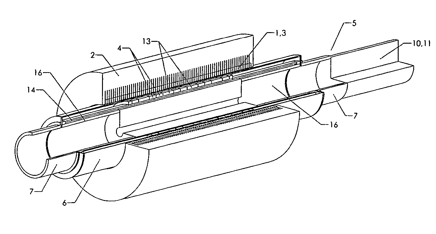
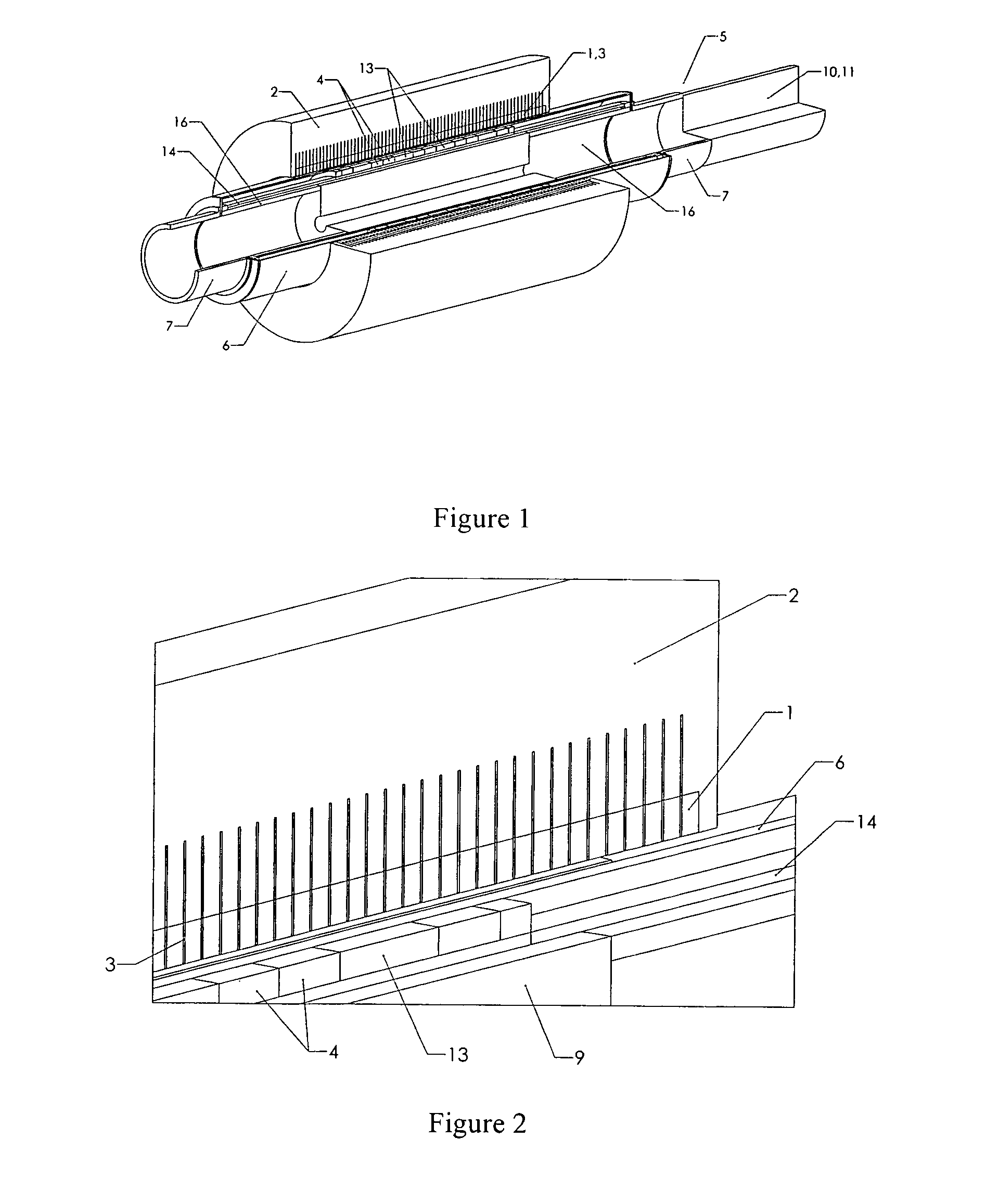
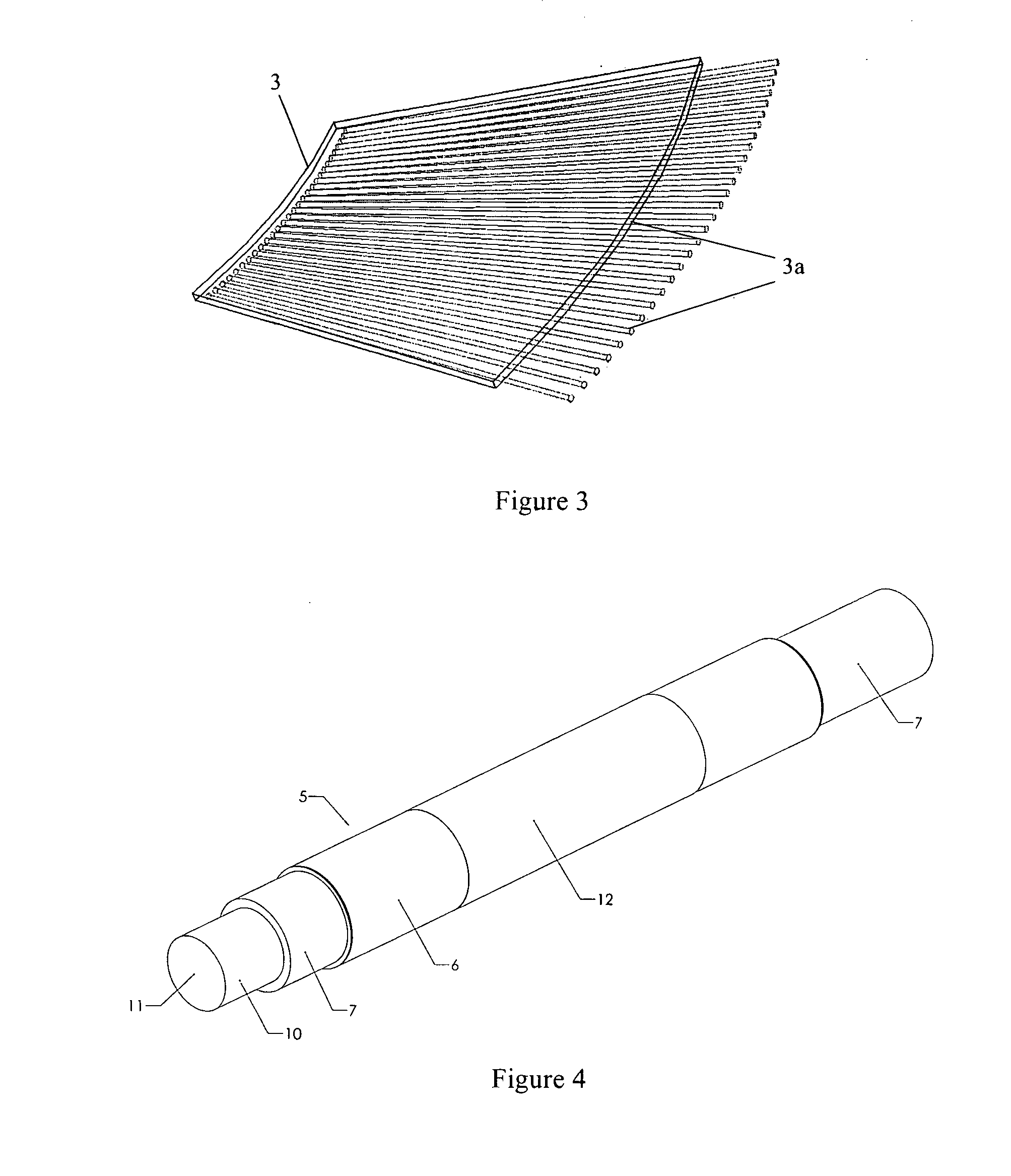
[0051] A first embodiment of a tubular machine according to the present invention will now be explained with reference to FIGS. 1 to 6. In this first embodiment a series of axially spaced armature coils 1 are contained in a tube-shaped radially outer member 2. The armature coils 1 are made of non-superconducting wire and are supported on a non-magnetic non-conducting structure. Since there are no magnetic teeth to guide the flux around the armature coils 1 they need to be stranded and transposed to avoid eddy current losses, which could be achieved by using litz wire, for example. A typical diameter for the armature coils 1 would be 700 mm. As a result of the high current density in the superconducting coils 4 there is no need for a magnetic core to be associated with the armature coils 1. The individual armature coils 1 are connected together to form a three-phase AC armature winding that is attached to a main power circuit connection (not shown). They are separated from each other...


PUM


Abstract

An improved synchronous tubular electrical machine comprises a radially outer member that has a substantially cylindrical inner surface and radially inner member that is substantially cylindrical and is coaxially disposed within the outer member such that it may move reciprocally relative to the outer member in the axial direction. A plurality of axially spaced circumferential armature coils are electrically insulated from one another and are formed as part of one of the outer member and the inner member. A plurality of axially spaced circumferential superconducting coils are formed as part of the other of the outer member and the inner member. During operation of the tubular machine, each superconducting coil is maintained in a superconducting state and an electrical current is supplied to each superconducting coil in such a manner that the current flowing around each coil is in the opposite direction to the current flowing around the coils adjacent to it. Such tubular machines may be significantly more efficient, have higher peak-mean power ratios and be much smaller than current permanent magnet based synchronous tubular electrical machines.

Description

BACKGROUND OF THE INVENTION [0001] 1. Field of the Invention [0002] The present invention relates to tubular electrical machines, and in particular to tubular electrical machines that are suitable for use either as direct drive generators or linear motors. [0003] 2. Description of the Related Art [0004] It is well known to use linear electrical machines either as generators, to convert an input of linear, usually reciprocating, motion into electrical power, or as motors, to produce a linear movement from an electrical power source. Most linear machines use a flat arrangement, which is based upon the workings of a conventional rotating machine that has been split open to form a flat surface. One of the disadvantages of this arrangement is that the mechanical support of the moving and flat parts can be quite complex. Another disadvantage is that, like rotating machines, flat linear machines usually contain end-windings that do not contribute to the electro-mechanical power conversion ...

Claims


Application Information

Patent Timeline
IPC IPC(8): H02K41/00H02K35/00
CPCH02K9/22H02K11/0005Y02E40/625H02K55/04H02K41/03Y02E40/60H02K11/012H02K9/227H02K1/34H02K55/02H02K33/06H02K35/00
Inventor LEWIS, CLIVELEFLEM, GRAHAM
Owner GE POWER CONVERSION
Why Eureka
Try Eureka