
Lighting circuit

a light-emitting circuit and circuit technology, applied in the direction of electric variable regulation, process and machine control, instruments, etc., can solve the problems of electromagnetic noise generating during noise generation, unstable status of discharge tubes, and inability to grasp the correlation characteristics between lamp voltages and optical outputs, etc., to achieve the effect of suppressing radiation nois

Inactive Publication Date: 2007-07-19
KOITO MFG CO LTD
View PDF10 Cites 35 Cited by
  • Summary
  • Abstract
  • Description
  • Claims
  • Application Information

AI Technical Summary

Benefits of technology

[0019]Embodiments of the present invention provide a lighting circuit capable of suppressing radiation noise even in such a case where a discharge tube is re-lighted, while a rising characteristic of an optical output from the discharge tube is not deteriorated.
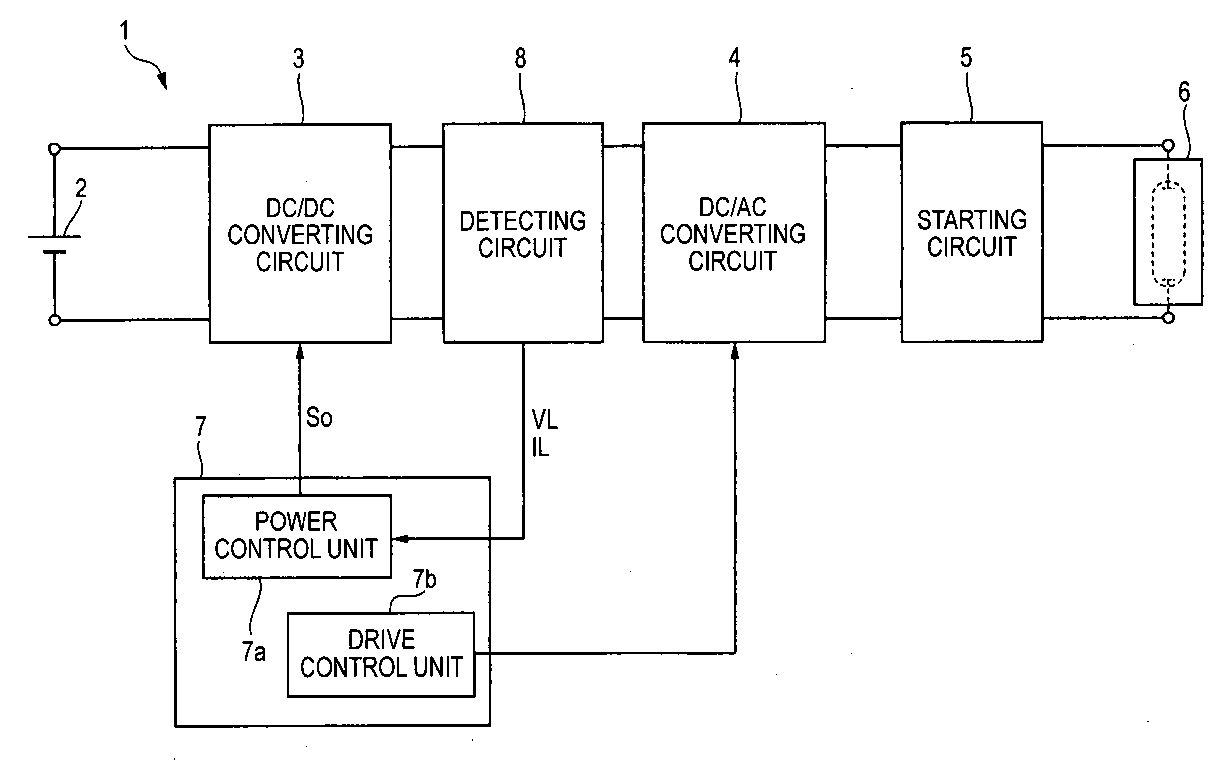
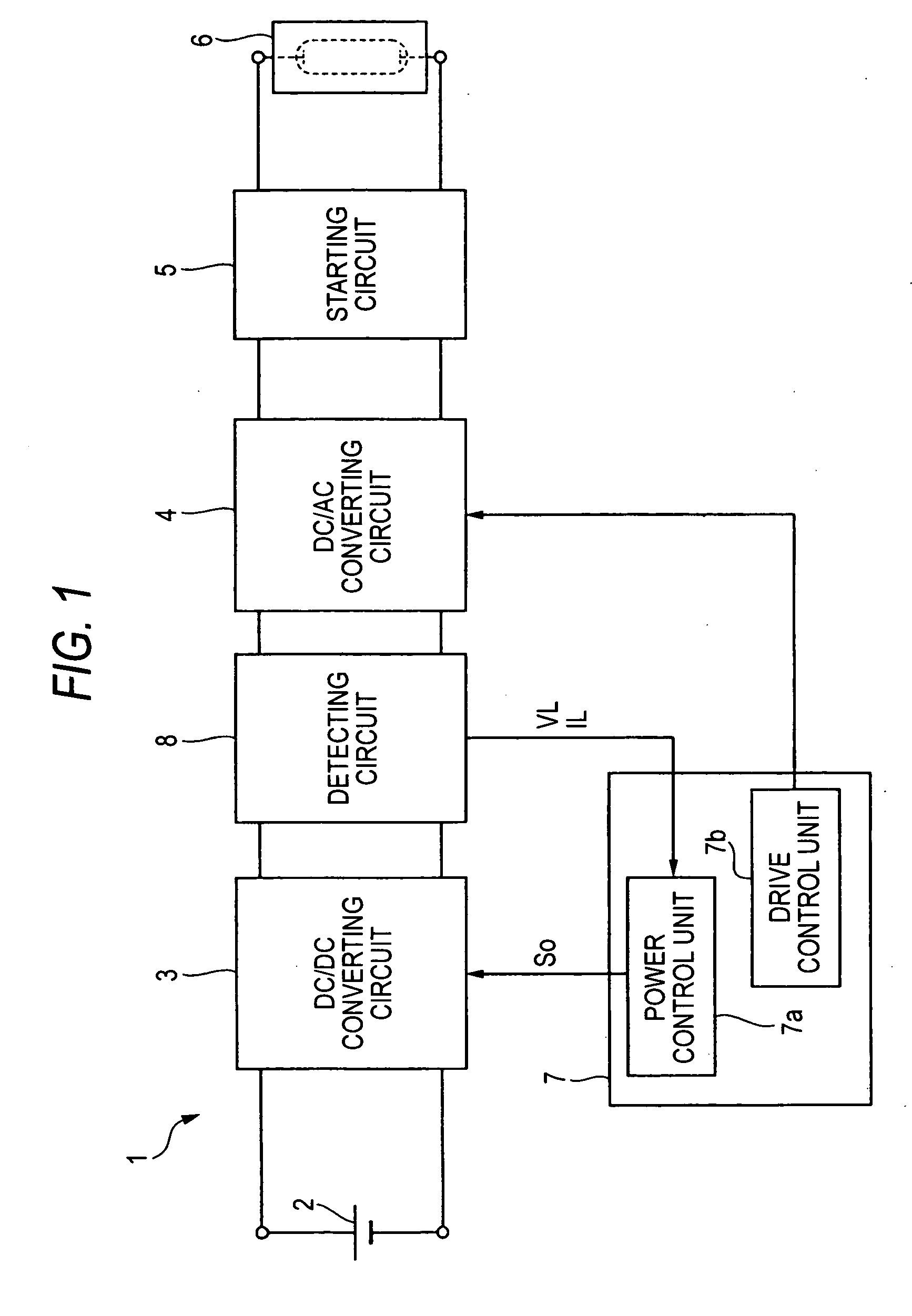
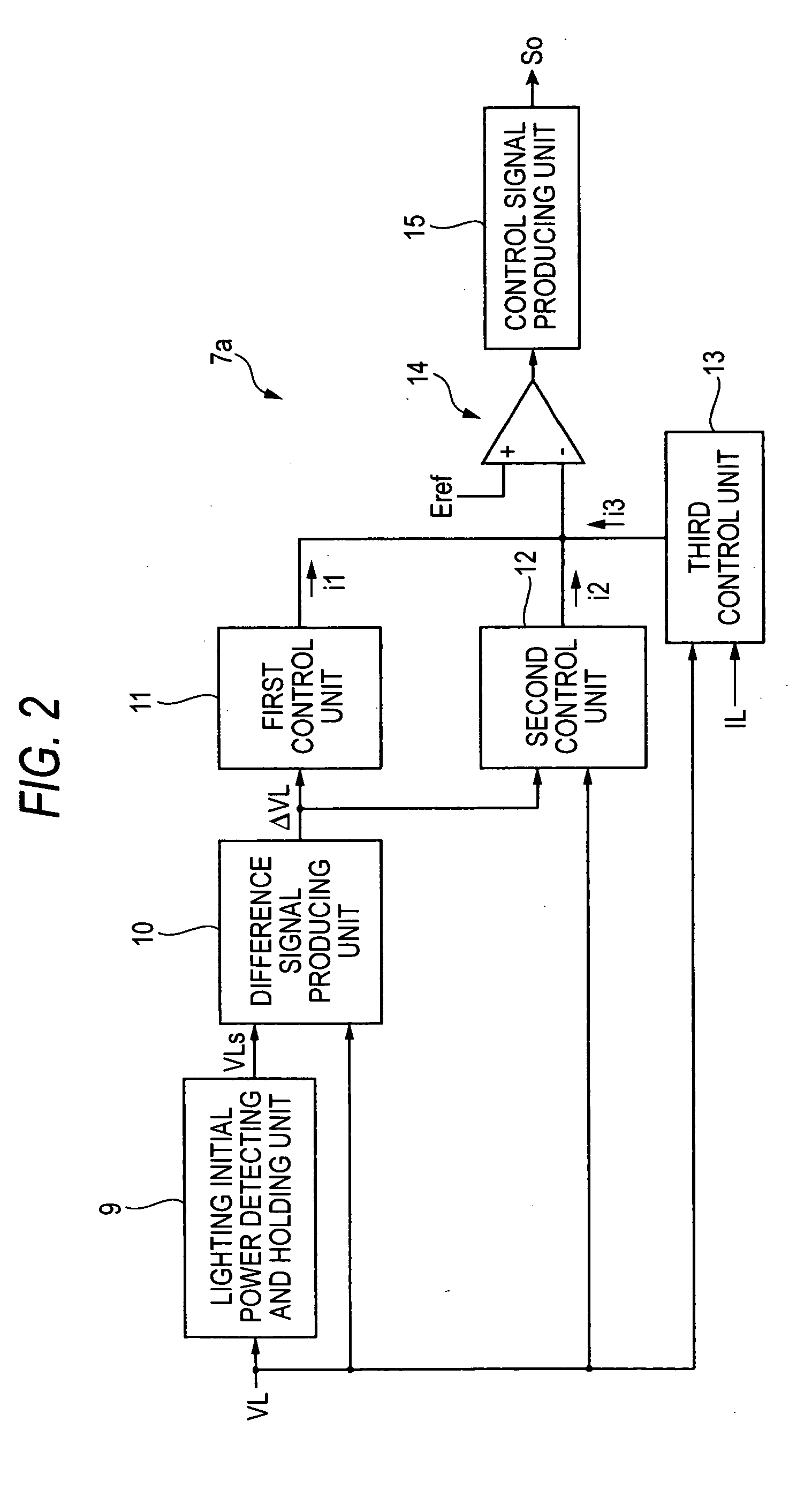
[0021]In accordance with the lighting circuit, in response to a control signal responding to the terminal voltage of the capacitance element, the output of the DC / DC converting circuit, namely the output power of the lighting circuit, is controlled. While the second discharging unit is coupled to the capacitance element, the second discharging unit provides such a discharging path for the capacitance element in response to turning-OFF of the input DC voltage. As a consequence, in accordance with this lighting circuit, when the input DC voltage is turned ON, the charging operation to the capacitance element is not disturbed, whereas when the input DC voltage is turned OFF, the electric charge in the capacitance element can be quickly discharged by the second discharging unit. As a result, the terminal voltage of the capacitance element can be reduced until the re-lighting operation of the discharge tube is started. When the discharge tube is re-lighted, high electric power can be provided to the discharge tube. As a consequence, in accordance with this lighting circuit, even when the discharge tube is re-lighted, the radiation noise can be suppressed while the overshoot in the rising characteristic of the optical output from the discharge tube is adjusted.
[0027]Various implementations may include one or more of the following advantages. For example, it is possible to provide a lighting circuit capable of suppressing radiation noise even in such a case where the discharge tube is re-lighted, while the rising characteristic of the optical output from the discharge tube is not deteriorated.

Problems solved by technology

Therefore, correlation characteristics between the lamp voltages and the optical outputs can be hardly grasped, and thus such a control method is required which is different from the transient power control method related to the discharge tubes containing mercury.
Within the noise generating time period Tn (for instance, 10 seconds to 20 seconds after lighting is started) started from the time instant “t3”, the status of the discharge tube becomes unstable, and thus there are some possibilities that electromagnetic noise may be radiated during this noise generating time period.
However, since a discharge tube containing no mercury cannot utilize the effects caused by mercury, the temperature of the luminous tube must be increased by increasing transient electric power supplied to the discharge tube.
As a consequence, in the transient power control operation of the discharge tube containing no mercury, lengthy time is necessarily required after lighting of the discharge tube is started until the discharge thereof becomes stable.
When electromagnetic noise generated during this long time period is radio noise, there are some risks that adverse influences may be given to various types of electronic appliances such as radio receivers and television receivers.
That is, larger amounts of electric power may be supplied to the discharge tube during the noise generating time period.
However, when a discharge tube is re-lighted (for example, when hot restart is carried out), namely, when lighting of the discharge tube is started from such a condition that the discharge tube is still warm, it is practically difficult to realize at the same time two operation of reducing noise and improving a rising characteristic of an optical output.

Method used


Image

  • Lighting circuit
  • Lighting circuit
  • Lighting circuit

Examples


first exemplary embodiment

[0092]Next, description is made of the second discharging unit 42 according to a first exemplary embodiment of the present invention. FIG. 7 is a circuit diagram showing an arrangement of the second discharging unit 42 according to the first exemplary embodiment of the present invention. The discharging unit 42 shown in FIG. 7 includes a diode 45 and resistor elements 46 and 47.

[0093]An anode of the diode 45 is connected to the capacitor 23, and a cathode of the diode 45 is connected to one terminal of the resistor element 46 and one terminal of the resistor element 47. The other terminal of the resistor element 46 is connected to a first power supply line 48, and the other terminal of the resistor element 47 is connected to a second power supply line (for example, ground line) 49.

[0094]A voltage is generated on the first power supply line in connection with a lamp voltage applied to the discharge tube. Concretely speaking, when an input DC voltage is turned ON, such a voltage which...

second embodiment

[0103]Next, a description is made of a second discharging unit 42A according to a second exemplary embodiment of the present invention. FIG. 10 is a circuit diagram showing an arrangement of the second discharging unit 42A according to the second exemplary embodiment of the present invention. The second discharging unit 42A shown in FIG. 10 can be employed instead of the second discharging unit 42 of the first exemplary embodiment. The second discharging unit 42A is different from the second discharging unit 42 as to the arrangement which is not provided with the resistance element 47 in the second discharging unit 42.

[0104]The second discharging unit 42A provides one discharging path (namely, discharging path constituted by diode 45 and resistor element 46) for the capacitor 23 in response to such a condition that the input DC voltage is turned OFF. Also, in the lighting circuit of this second exemplary embodiment, a similar merit to the lighting circuit of the first exemplary embo...

third exemplary embodiment

[0105]Next, description is made of a second discharging unit 42B according to a third exemplary embodiment of the present invention. FIG. 11 is a circuit diagram showing an arrangement of the second discharging unit 42B according to the third exemplary embodiment of the present invention. The second discharging unit 42B shown in FIG. 11 can be employed instead of the second discharging unit 42 of the first exemplary embodiment. The second discharging unit 42B is different from the second discharging unit 42 as to the arrangement which is not provided with the resistance element 46 in the second discharging unit 42, and is different from the second discharging unit 42 as to the arrangement in which the cathode of the diode 45 and one terminal of the resistor element 47 are connected to the first power line 48.

[0106]In the first exemplary embodiment, when the input DC voltage is turned OFF, the first power supply line 48 is grounded. In this third exemplary embodiment, when the input ...


PUM


Abstract

A lighting circuit includes a DC / DC converting circuit for boosting an input DC voltage so as to produce boosted DC power, a detecting circuit for producing a detection signal in response to the output voltage of the DC / DC converting circuit, a DC / AC converting circuit for producing AC power to be supplied to the discharge tube from the boosted DC power, a starting circuit for starting up the discharge tube, and a control circuit for receiving the detection signal from the detecting circuit. The control circuit contains a capacitor which is charged based upon the detection signal, a first discharging unit for discharging the capacitor, a second discharging unit for providing a discharging path for the capacitor in response to turning-OFF of the input DC voltage, and a signal producing unit for producing a control signal used to adjust the output of the DC / DC converting circuit in response to a terminal voltage of the capacitor.

Description

[0001]This application claims priority to Japanese Patent Application No. 2006-010360, filed Jan. 18, 2006, in the Japanese Patent Office. The priority application is incorporated by reference in its entirety.TECHNICAL FIELD[0002]The present disclosure is related to a lighting circuit for lighting a discharge tube used in a vehicle.RELATED ART[0003]In the case where discharge tubes are employed for illumination of vehicles, since luminous flux thereof must be quickly raised after lighting of the discharge tubes has been started, transient power control operations are carried out as follows. That is, just after the discharge tubes are lighted, electric power higher than electric power supplied when the discharge tubes are lighted under a stationary condition is supplied to the discharge tubes, and the supplied electric power is reduced in accordance with time elapses. As to the discharge tubes, two different types of discharge tubes are known in the technical field. In one type of di...

Claims


Application Information

Patent Timeline
Patent Type & Authority Applications(United States)
IPC IPC(8): H05B41/36
CPCH05B41/384Y02B20/206H05B41/386Y02B20/00Y10S315/07
Inventor SUZUKI, TOMOKAZU
Owner KOITO MFG CO LTD
Learn More