Image capturing apparatus and image capturing system

Inactive Publication Date: 2007-07-19
CANON KK
View PDF5 Cites 8 Cited by
  • Summary
  • Abstract
  • Description
  • Claims
  • Application Information

AI Technical Summary

Benefits of technology

[0008]The present invention has been made on the basis of the recognition of the above prob

Problems solved by technology

However, due to the characteristic fluctuations of sensors, the predetermined signal range could not be attained even with the gain adjustment condu

Method used


Image

  • Image capturing apparatus and image capturing system
  • Image capturing apparatus and image capturing system
  • Image capturing apparatus and image capturing system

Examples


Example

First Embodiment

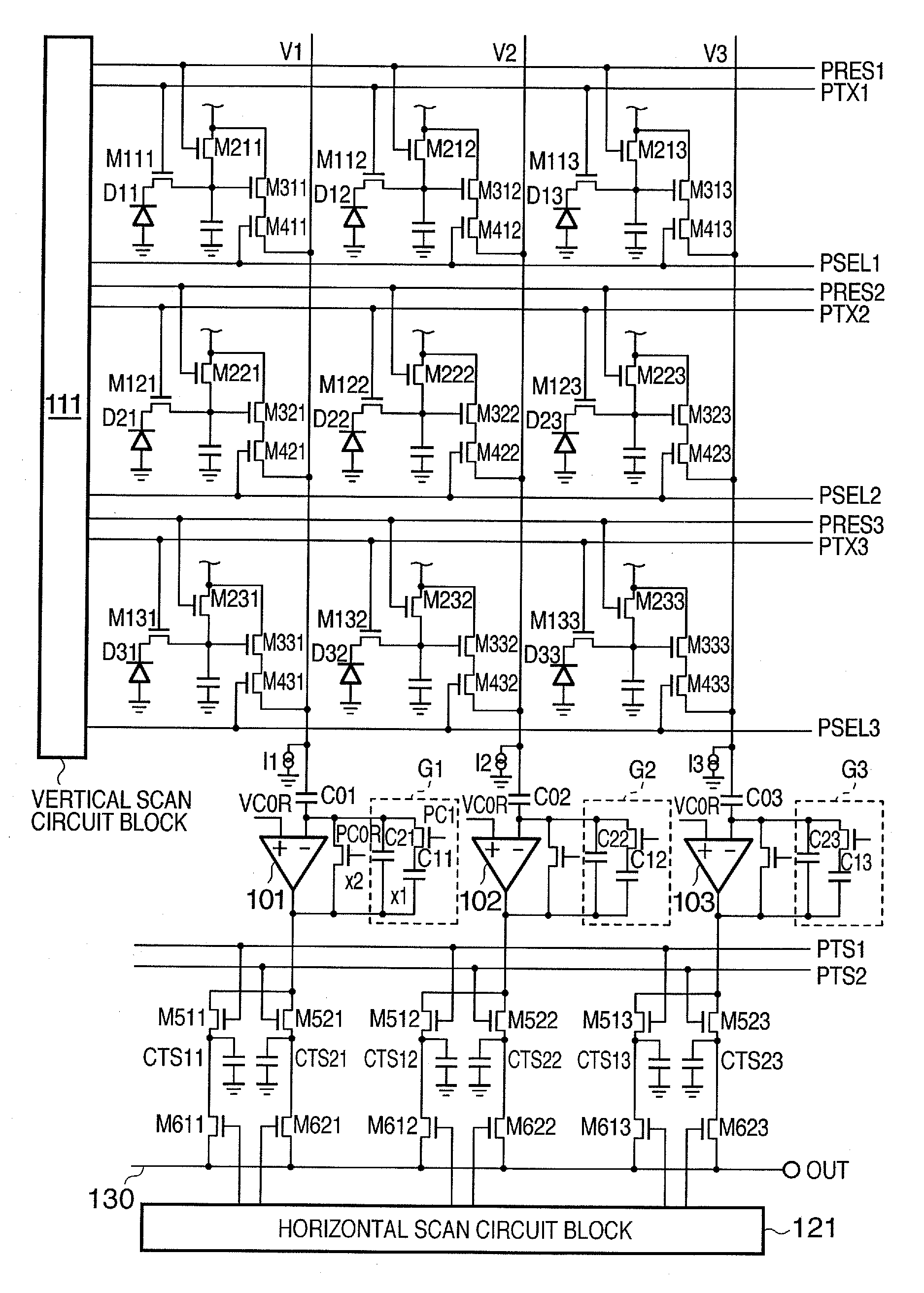
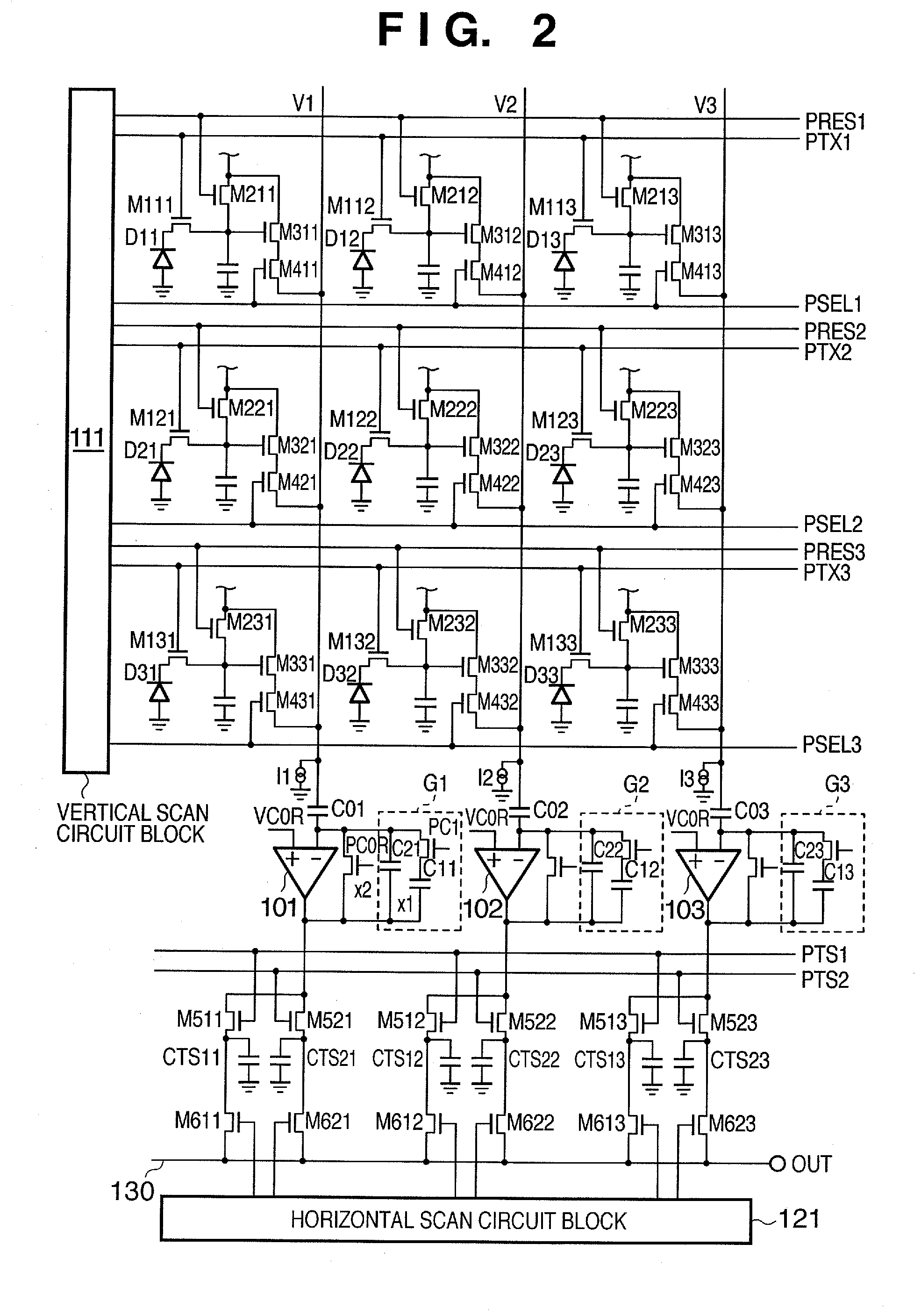
[0026]FIG. 2 is an equivalent circuit diagram of the image capturing apparatus according to the preferred first embodiment of the present invention. Each circuit element of the image capturing apparatus in the present embodiment is not limited to this arrangement, but is formed on a semiconductor substrate such as a single crystal silicon substrate through the use of a manufacturing technique for manufacturing semiconductor integrated circuits. Each pixel has a photoelectric conversion element and components such as switching elements and capacitances. For simplicity, FIG. 2 shows an image array with 3 rows and 3 columns, but the size of the image array is not limited to these dimensions.

[0027]The configuration of the image capturing apparatus in the present embodiment will be explained with reference to FIG. 2. In this case, photodiodes D11-D33, which act as photoelectric conversion elements that generate optical signals, have their anode side grounded. The cathode ...

Example

Second Embodiment

[0064]FIG. 5 is a drawing of an equivalent circuit diagram of the image capturing apparatus of the preferred second embodiment. The output terminal of an operational amplifier 101 is connected to the first signal holding unit group for temporarily holding the optical signal through the optical signal transfer switch, and to the second signal holding unit group for temporarily holding the noise signal through the noise signal transfer switch. In FIG. 5, the output terminal of the operational amplifier 101 is connected to a capacitor CTs11 of the first signal holding unit group through an optical signal transfer switch M511. The output terminal of the operational amplifier 101 is connected to a capacitor CTn11 of the second signal holding unit group through a noise signal transfer switch M711. In addition, the output terminal of the operational amplifier 101 is connected to a capacitor CTs21 of the first signal holding unit group through an optical signal transfer swi...


PUM


Abstract

The present invention provides an image capturing apparatus, which comprises a plurality of photoelectric converter-containing pixels that are positioned horizontally and vertically and a gain circuit, has a gain controller that can control the gain of the gain circuit in N stages (where N is an integer equal to or greater than 2). The gain circuit outputs each of a plurality of signals given by the product of the output signal from one of the plurality of pixels and the gain in each stage of the N stages.

Description

BACKGROUND OF THE INVENTION[0001]1. Field of the Invention[0002]The present invention relates to an image capturing apparatus that converts light into electrical signals, and to an image capturing system that comprises the image capturing apparatus.[0003]2. Description of the Related Art[0004]Conventionally, image capturing systems have set gains close to the saturation value in order to improve the S / N ratio. However, due to the characteristic fluctuations of sensors, the predetermined signal range could not be attained even with the gain adjustment conducted in the factory. Further, there were cases in which attempting to attain the predetermined signal range would result in a deteriorating S / N ratio. Here, N (noise) refers to the circuit noise existing outside of the sensor.[0005]Japanese Patent Application Laid-Open No. 2003-101881 discloses a method to enlarge the dynamic range of light detection by applying different gains to the ordinary signal and to the excessive signal res...

Claims


Application Information

Patent Timeline
IPC IPC(8): H04N5/20H04N5/335H04N5/341H04N5/355H04N5/357H04N5/369H04N5/374H04N5/376
CPCH04N5/2352H04N5/355H04N5/378H04N5/3742H04N5/3575H04N23/72H04N25/57H04N25/616H04N25/767H04N25/75
Inventor YAMAUCHI, MAKIKO
Owner CANON KK
Why Eureka
Try Eureka