
Mobile station, base station, communication system, and communication method

a technology of applied in the field of mobile station, base station, communication system and communication method, can solve the problems of severe delay requirements in the communication quality of audio data and video information, and achieve the effect of reducing the delay time due to packet data retransmission

Inactive Publication Date: 2007-07-19
MITSUBISHI ELECTRIC CORP
View PDF6 Cites 55 Cited by
  • Summary
  • Abstract
  • Description
  • Claims
  • Application Information

AI Technical Summary

Benefits of technology

[0011] As a result, since the mobile station can notify a transmission request for permission to transmit next packet data to the base station efficiently, a delay time which occurs due to retransmission of packet data can be shortened.
[0013] As a result, since the mobile station can notify a transmission request for permission to transmit next packet data to the base station efficiently, a delay time which occurs due to retransmission of packet data can be shortened.
[0015] As a result, since the mobile station can notify a transmission request for permission to transmit next packet data to the base station efficiently, a delay time which occurs due to retransmission of packet data can be shortened.

Problems solved by technology

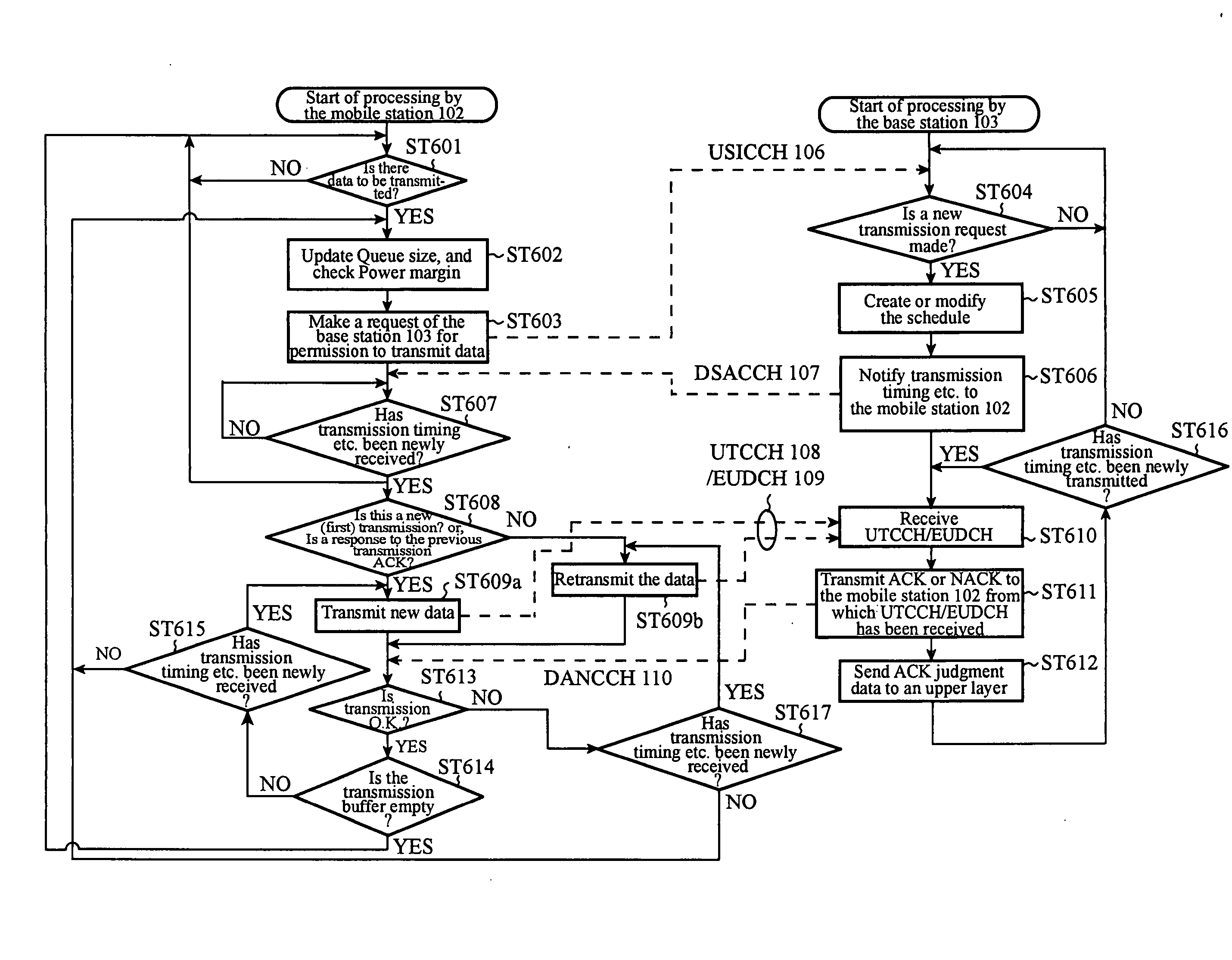
A problem with the transmission method disclosed in the above-mentioned reference is that since it takes as much as 10 ms·4=40 ms to carry out a sequence of transmission processes: (transmission request->assignment->data transmission->notification of judgment of reception), when the transmission data are not correctly received by the base station, that is, when judgment of so-called NACK is continued and retransmission of packet data is carried out a large number of times, the transmission delay time becomes large and this results in degradation in the communication quality of audio data and video information having severe requirements on delay.

Method used


Image

  • Mobile station, base station, communication system, and communication method
  • Mobile station, base station, communication system, and communication method
  • Mobile station, base station, communication system, and communication method

Examples


embodiment 1

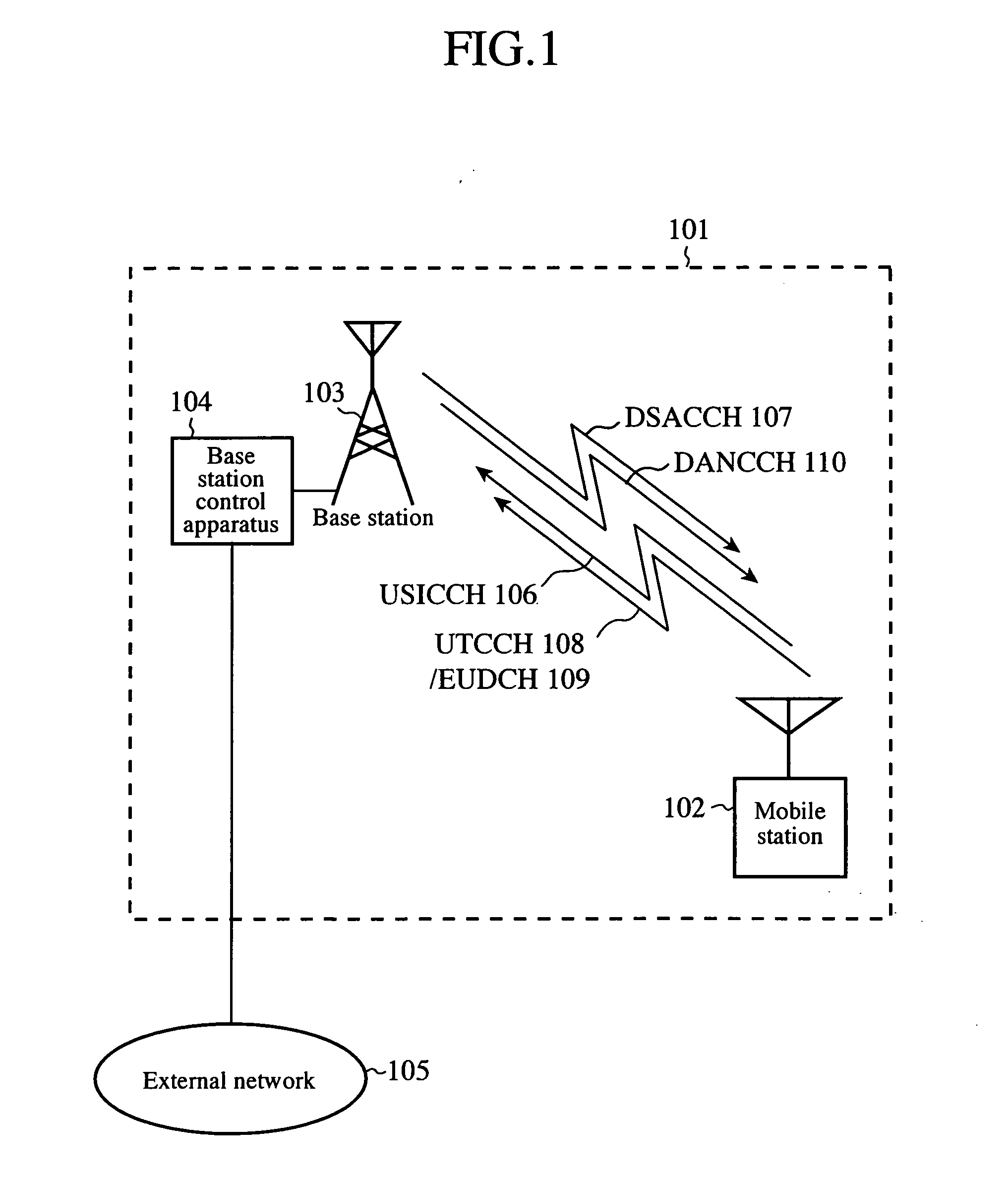
[0038]FIG. 1 is a schematic diagram showing the structure of a communications system 101 in accordance with embodiment 1 of the present invention.

[0039] As shown in the figure, the communications system 101 is provided with a mobile station 102, a base station 103, and a base station control apparatus 104. The base station 103 can communicate with a plurality of mobile stations 102 staying in a fixed area. This area in which the base station 103 can communicate with a plurality of mobile stations is called a sector or cell. For simplicity's sake, only one mobile station 102 is shown in the figure.

[0040] The base station control apparatus 104 is connected to an external network 105, such as a public telephone network and the Internet, and relays packet communications between the base station 103 and the external network 105.

[0041] Data communications between the mobile station 102 and the base station 103 are carried out using a plurality of channels. As shown in this figure, upli...

embodiment 2

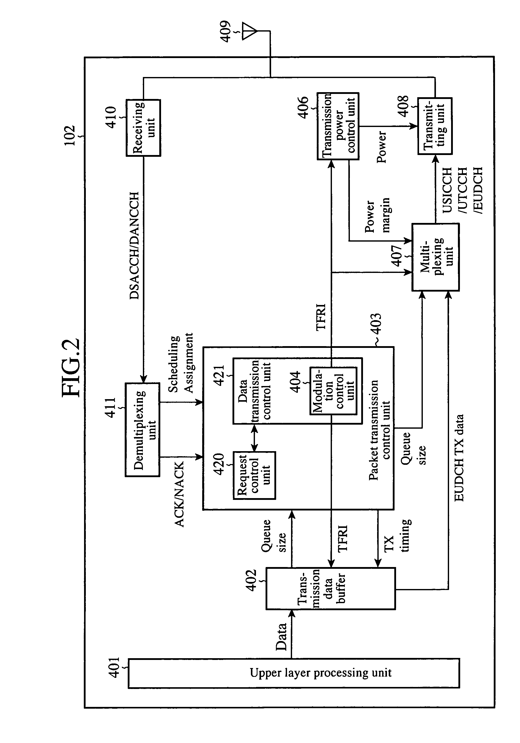
[0131]FIG. 8 is a block diagram showing the structure of a mobile station 102 in accordance with embodiment 2 of the present invention. The same numerals as shown in FIG. 2 denote the same components as those of embodiment 1. FIG. 9 is a block diagram showing the structure of a base station 103 in accordance with embodiment 2 of the present invention. The same numerals as shown in FIG. 3 denote the same components as those of embodiment 1.

[0132] In accordance with embodiment 2, information which the mobile station 102 transmits to the base station 103 using the USICCH 106 includes a transmission rate change request (Rate Request) RR for transmission in addition to transmission data size (Queue Size) and transmission power margin information (Power Margin) indicating a margin for the maximum transmission power of the mobile station 102, which are the same as those explained in embodiment 1.

[0133] Information which the base station 103 transmits to the mobile station 102 using the D...

embodiment 3

[0160] Embodiment 3 is an example in which embodiment 1 or 2 is applied to a parallel retransmission system (N channel Stop and Wait: N (a natural number) is a division number) which is an on-demind type channel assignment system. Each channel used for data transmission and reception between the mobile station 102 and the base station 103 is time-divided periodically, and each divided channel is assigned to data to transmission and reception of data, and data retransmission processing is independently carried out in each assignment.

[0161] A range of concrete values of N and a concrete method of notifying N are defined by the 3GPP specifications. Assume that the division number N is determined based on exchanges of information among the base station control apparatus 104, base station 103, and mobile station 102 when channels are set up at a time of start of communications or when communications are being carried out. As an alternative, the base station 103 can independently determi...


PUM


Abstract

In a communications system, a mobile station sends a transmission request for permission to transmit packet data to a base station and transmits the packet data to the base station according to transmission schedule information about a transmission schedule which the base station determines in response to the transmission request, and the base station transmits a result of judgment of reception of packet data which it has received to the mobile station. The mobile station transmits transmission request information about new packet data which it will transmit to the base station next before completing reception of a result of judgment of reception of packet data which the mobile station has transmitted to the base station from the base station. As a result, since the mobile station can notify a transmission request for permission to transmit next packet data to the base station efficiently, a delay time which occurs due to retransmission of packet data can be shortened.

Description

FIELD OF THE INVENTION [0001] The present invention relates to a mobile station and a base station which communicate packet data to each other in a CDMA (Code Division Multiple Access) mobile communications system, the communications system, and a communications method. BACKGROUND OF THE INVENTION [0002] As a high-speed mobile communications method which adopts a CDMA system, telecommunications standards called a third generation is adopted by the International Telecommunications Union (ITU) as IMT-2000. A W-CDMA (FDD: Frequency Division Duplex) commercial service was started in Japan in 2001. A W-CDMA (FDD) method is a third-generation mobile communications method, and aims at acquiring a maximum transmission speed of about 2 Mbps per mobile station. For the W-CDMA (FDD) method, the first specification is determined by the release 1999th edition summarized in 1999 by the standardization organization 3GPP (3rd. Generation Partnership Project). [0003] Various written standards are di...

Claims


Application Information

Patent Timeline
Patent Type & Authority Applications(United States)
IPC IPC(8): H04B7/216H04L12/56H04J13/00H04W36/16H04W72/14H04W74/00
CPCH04W72/1284H04W72/1268H04W72/21
Inventor NIWANO, KAZUHITO
Owner MITSUBISHI ELECTRIC CORP
Learn More