Reception apparatus

a technology of reception apparatus and receiver, which is applied in the field of transmission, can solve the problems of ignoring the synchronization of channels in the same frequency, and the structure encounters difficulty in achieving, and achieves the effect of accurately estimating channels

Inactive Publication Date: 2007-07-19
PANASONIC INTELLECTUAL PROPERTY CORP OF AMERICA
View PDF56 Cites 49 Cited by
  • Summary
  • Abstract
  • Description
  • Claims
  • Application Information

AI Technical Summary

Benefits of technology

[0007] The present invention aims to provide a reception apparatus that can estimate channels accurately and with ease from multiplexed modulation signals.
[0014] The foregoing structure multiplexes the modulation signals of a plurality of channels to the same frequency, thereby increasing the data transmission rate. At the same time, an antenna for demodulation is selected by using the phase difference and the received signal strength intensity as parameters, so that the antenna in the best condition can be selected. As a result, the data transmission quality can be improved.
[0021] The foregoing structure multiplexes the modulation signals of a plurality of channels to the same frequency, thereby increasing the data transmission rate. At the same time, an antenna for demodulation is selected using the phase difference and the received signal strength intensity as parameters, so that the antenna in the best condition can be selected. As a result, the data transmission quality can be improved, and a propagation path can be estimated with ease.
[0028] The foregoing structure multiplexes the modulation signals of a plurality of channels to the same frequency, thereby increasing the data transmission rate. At the same time, the reception apparatus receives the symbol, which is used for estimating time-synchronization, transmitted through one channel from the transmission apparatus, thereby obtaining the time-synchronization common to the plurality of channels. The most reliable signal is selected out of time-synchronization signals supplied from the respective antennas, so that an estimation accuracy can be increased.
[0034] The foregoing structure multiplexes the modulation signals of a plurality of channels to the same frequency, thereby increasing the data transmission rate. At the same time, the reception apparatus receives the symbol, which is used for estimating a frequency offset, transmitted through one channel from the transmission apparatus, so that the frequency offset common to the signals of the plurality of channels can be estimated. The frequency offset estimation unit is prepared to each one of the antennas, and the signal supplied from the antenna, which has the best reception received signal strength intensity, is used for removing the frequency offset. As a result, the frequency offset can be accurately removed.
[0035] As discussed above, in a communication method which multiplexes modulation signals of a plurality of channels to the same frequency band, a reception apparatus selects an antenna, which has the best environment, by estimating a radio-wave propagation environment, such as a received signal strength intensity, from a reception signal. The reception apparatus then uses symbols, included in the signals supplied from the selected antenna, for estimating a phase difference, time-synchronization, or removing a frequency offset. Through multiplexing the modulation signals of a plurality of channels to the same frequency band, the foregoing operation and structure advantageously allow increasing the data transmission rate, and also allow the reception apparatus to demultiplex the multiplexed modulation signals with ease.

Problems solved by technology

However, the foregoing conventional structure gives no thought to the synchronization between channels in the same frequency band as well as a frequency offset.
As a result, this structure encounters the difficulty of achieving the most important factor in order to demultiple a multiplexed signal, namely, obtaining an accuracy of estimating channels.

Method used


Image

  • Reception apparatus
  • Reception apparatus
  • Reception apparatus

Examples


exemplary embodiment 1

[0125] In a transmission method where modulation signals of a plurality of channels are multiplexed to the same frequency band, at the time when a demodulation symbol is inserted in a channel, in another channel symbol, the same phase and quadrature signals in the in-phase-quadrature plane are made to be zero signals. The foregoing method and a transmission apparatus as well as a reception apparatus employed in the method are described in this first embodiment.

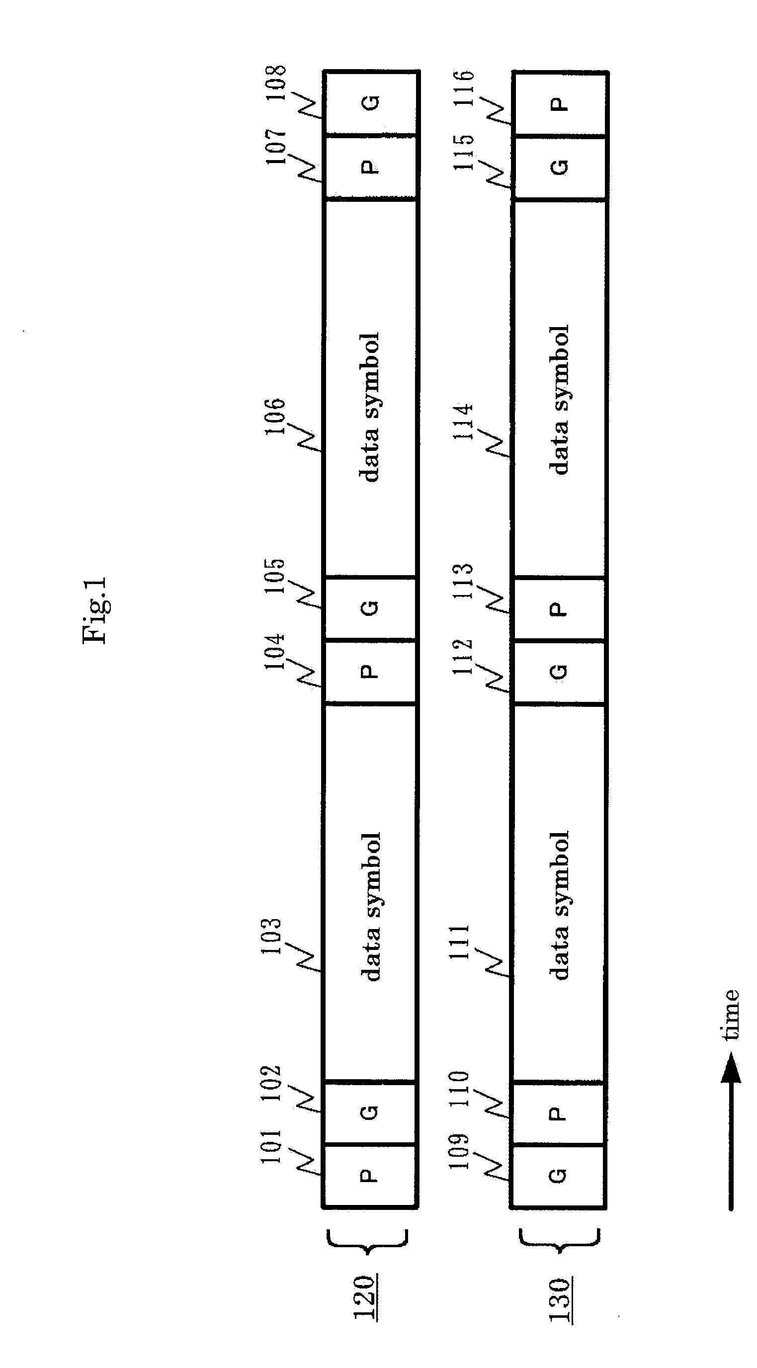
[0126]FIG. 1 shows frame structure 120 of channel A and frame structure 130 of channel B along a time axis. Channel A has pilot symbols 101, 104, 107, guard symbols 102, 105, 108, and data symbol 103, 106. Data symbols, for instance, have undergone QPSK (quadrature phase shift keying) modulation. Channel B has guard symbols 109, 112, 115, pilot symbols 110, 113, 116, and data symbols 111, 114. Data symbols, for instance, have undergone QPSK modulation.

[0127] Pilot symbol 101 of channel A and guard symbol 109 of channel B are...

exemplary embodiment 2

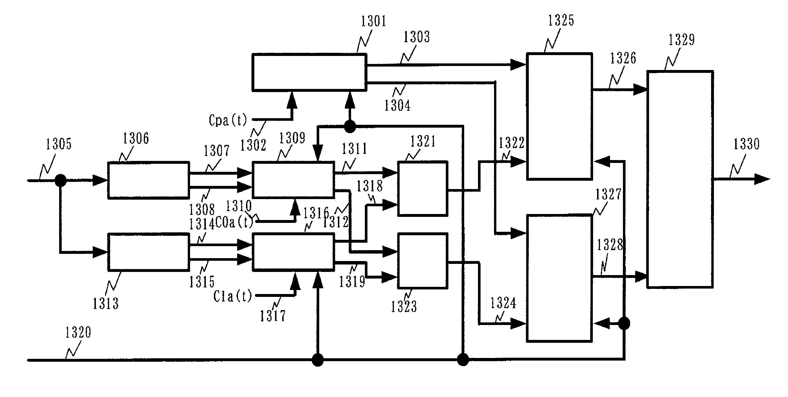
[0239] In this second embodiment, a reception apparatus is described. The reception apparatus comprising the following elements: [0240] a received signal strength intensity estimation unit for estimating a reception received signal strength intensity of a signal received by respective antennas and outputting an estimation signal of the reception received signal strength intensity of the reception signal; [0241] a phase difference estimation unit for receiving a transmission path variation estimation signal of a channel of the respective antennas, finding a phase difference of the transmission path variation estimation signal between the respective antennas, and outputting a phase difference signal; and [0242] a signal selection unit for receiving a reception quadrature baseband signal of the respective antennas, a transmission path variation estimation signal of each channel of the respective antennas, a reception electric field estimation signal of the reception signal, the phase d...

exemplary embodiment 3

[0310] The third embodiment describes a transmission method, which handles the following frame structure of signals transmitted from respective antennas: [0311] a symbol for estimating transmission path variation is inserted into the frame; [0312] the symbols is multiplied by a code; [0313] the symbols of the respective antennas are placed at an identical time; and [0314] the codes of the respective antennas are orthogonal to each other. The third embodiment also describes a transmission apparatus and a reception apparatus both used in the foregoing transmission method.

[0315]FIG. 11 shows frame structure 1120 in accordance with spread spectrum communication method A, and frame structure 1130 in accordance with spread spectrum communication method B. Pilot symbols 1101, 1103, 1105 of spread spectrum communication method A are multiplied by a code. Data symbols 1102, 1104 of spread spectrum communication method A are multiplied by a code.

[0316] Pilot symbols 1106, 1108, 1110 of spre...


PUM


Abstract

A reception apparatus includes a plurality of antennas for receiving modulation signals of channels in the same frequency band, an received signal strength intensity estimation unit for estimating the reception received signal strength intensity of each reception signal, transmission path fluctuation estimation units for estimating a transmission path fluctuation of each channel of the reception signal, phase difference estimation units for calculating a phase difference of the transmission path fluctuation estimation signal of a predetermined channel of each antenna and outputting it as a phase difference signal, and a signal selection unit for selecting and outputting a reception quadrate baseband signal for isolating a signal of each channel from the reception signals and a transmission path fluctuation estimation signal of each channel. Thus, by isolating and demodulating a plurality of muliplexed modulated signals received, it is possible to improve the data transmission rate.

Description

[0001] This application is a continuation of U.S. patent application Ser. No. 10 / 486,894, filed Feb. 17, 2004, the contents of which are incorporated herein by reference.TECHNICAL FIELD [0002] The present invention relates to a transmission method for multiplexing modulation signals of a plurality of channels to the same frequency band, a transmission apparatus and a reception apparatus. BACKGROUND ART [0003] This kind of transmission method and reception method have been available such as the ones disclosed in Japanese Patent Application Non-Examined Publication No. 2002-44051. FIG. 87 illustrates the transmission method and the reception method disclosed in the foregoing publication. [0004] In FIG. 87, first space-time encoder STE1 (8705) receives first data block b1 [n, k], and second space-time encoder STE2 (8707) receives second data block b2 [n, k], and two signals coded by encoders STE1 and STE 2 respectively are modulated by inverse fast Fourier transformers IFFT (8708-8711)...

Claims


Application Information

Patent Timeline
Patent Type & Authority Applications(United States)
IPC IPC(8): H04K1/10H04B1/707H04B1/7073H04L27/18H04B1/711H04B7/06H04B7/08H04J11/00H04J99/00H04L1/06H04L25/02H04L27/26H04L27/36
CPCH04B7/0632H04L27/14H04B7/0689H04B7/0697H04B7/082H04L1/0618H04L25/0206H04L27/2601H04L27/2602H04L27/2657H04L27/2627H04L27/04H04B7/0413H04L27/06H04L27/12H04B7/0671H04L5/0048H04L27/18H04L25/0204H04L27/0008H04L5/003H04L69/22H04L5/0023H04L27/2659H04L27/2691H04L27/2695H04W52/52H04W72/0453H04B7/06H04B7/0626
Inventor MURAKAMI, YUTAKAORIHASHI, MASAYUKIMATSUOKA, AKIHIKO
Owner PANASONIC INTELLECTUAL PROPERTY CORP OF AMERICA
Why Eureka
Try Eureka