
Rubbing system for alignment layer of LCD and method thereof

Active Publication Date: 2007-07-19
LG DISPLAY CO LTD
View PDF1 Cites 1 Cited by
  • Summary
  • Abstract
  • Description
  • Claims
  • Application Information

AI Technical Summary

Benefits of technology

[0010]An advantage of the present invention is to provide a rubbing system for an alignment layer of a liquid crystal display (LCD) device capable of applying a uniform alignment controlling force onto an alignment layer by uniformly maintaining a gap between the alignment layer and a rubbing roll by simultaneously lifting and lowering a rubbing table and the rubbing roll, and a method thereof.
[0011]Another advantage of the present invention is to provide a rubbing system for an alignment layer of a liquid crystal display (LCD) device capable of enhancing rubbing efficiency by selectively driving a rubbing table or a rubbing roll according to an alignment controlling force applied to an alignment layer, and a method thereof.
[0012]Yet another advantage of the present invention is to provide a method for fabricating a liquid crystal display (LCD) device using the rubbing system.

Problems solved by technology

However, the method for processing an alignment layer by rubbing has the following problems.
As width and weight of the rubbing roll are increased, uniformly maintaining a pressure applied to a mother substrate is difficult.
Lack of uniform pressure applied to the mother substrate can result in defects on the alignment layer.

Method used


Image

  • Rubbing system for alignment layer of LCD and method thereof
  • Rubbing system for alignment layer of LCD and method thereof
  • Rubbing system for alignment layer of LCD and method thereof

Examples


Embodiment Construction

[0032]Reference will now be made in detail to embodiments of the present invention, examples of which are illustrated in the accompanying drawings.

[0033]A liquid crystal display (LCD) device displays images on a screen by using the refractive index anisotropy of liquid crystal. The LCD device displays an image by changing the alignment direction of liquid crystal molecules according to a voltage applied to a liquid crystal layer, and thus controls light transmittance that passes through the liquid crystal layer.

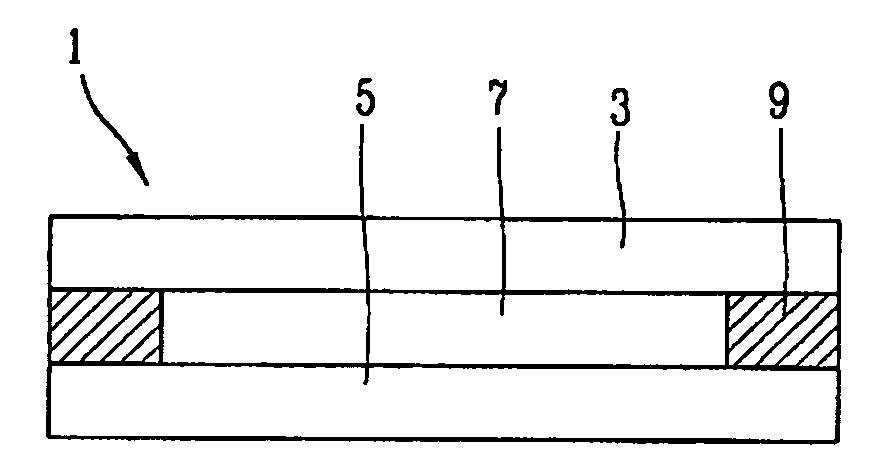
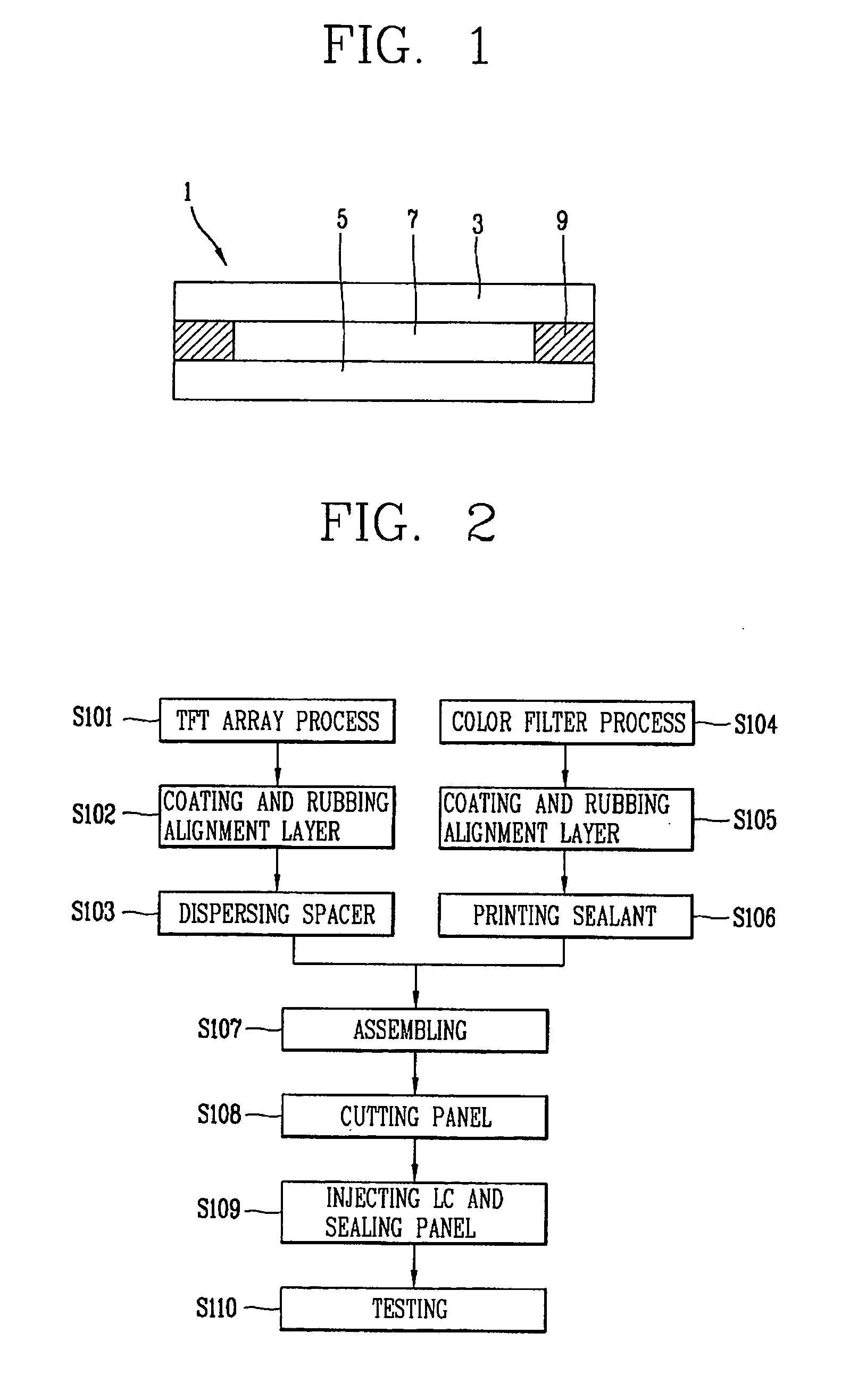
[0034]FIG. 1 is a schematic view showing a structure of a liquid crystal display (LCD) device according to the present invention;

[0035]As shown in FIG. 1, the LCD device I comprises a lower substrate 5, an upper substrate 3, and a liquid crystal layer 7 formed therebetween. The lower substrate 5 may be a driving device array substrate, and may include a plurality of pixels (not shown) and a driving device, such as a thin film transistor (TFT) formed (not shown) near each pixe...


PUM


Abstract

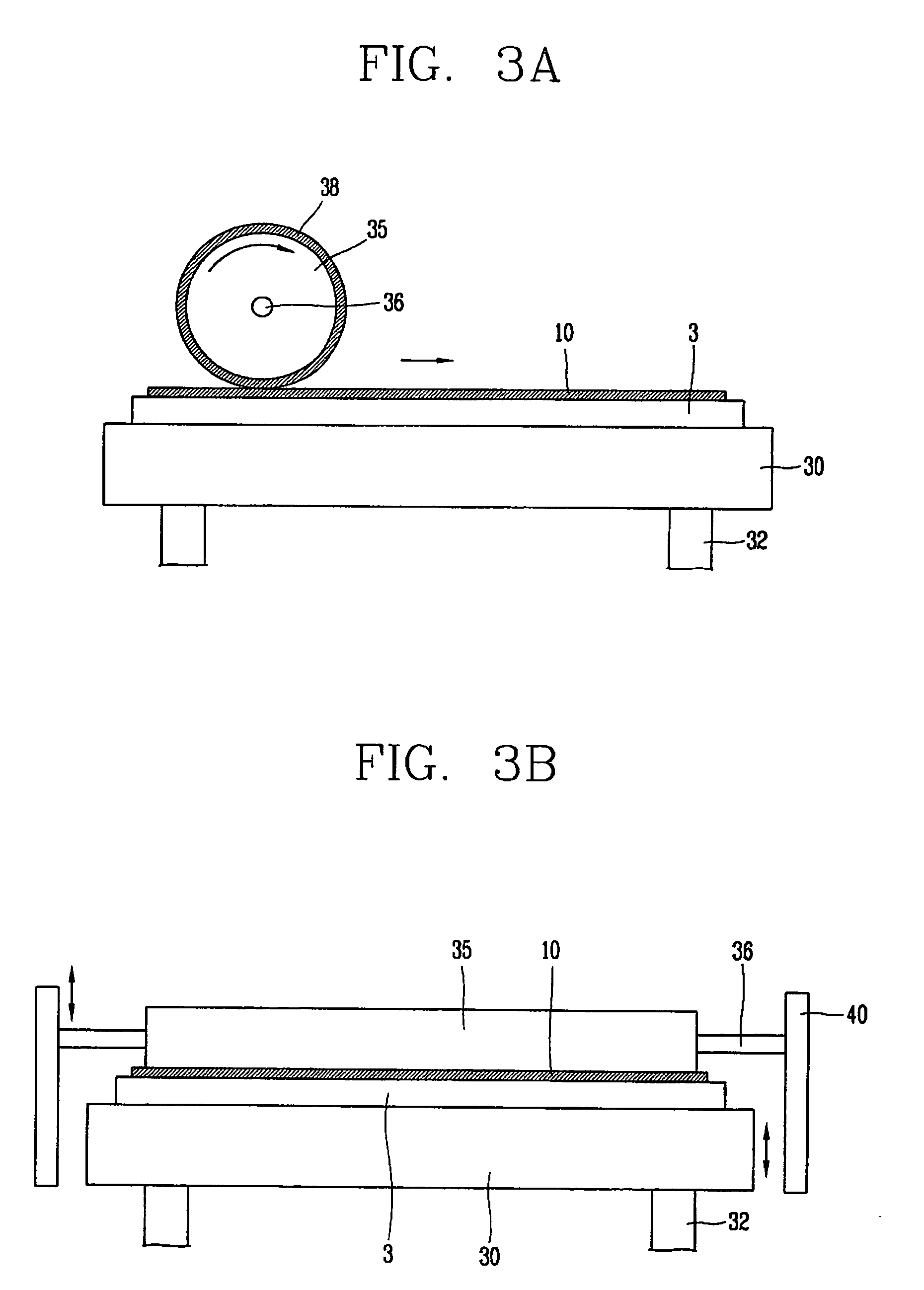
A rubbing system for an alignment layer of a liquid crystal display (LCD) device, comprises: a rubbing table on which a substrate having an alignment layer thereon is positioned; a rubbing roll on which a rubbing material is wound, substantially positioned on the rubbing table thus to substantially contact the alignment layer, for rubbing the alignment layer by rotation of the rubbing roll; and a controlling unit for controlling the alignment layer to be rubbed by substantially contacting the rubbing roll onto the alignment layer by simultaneously lifting and lowering a rubbing table and the rubbing roll according to an alignment controlling force to be applied to the alignment layer.

Description

[0001]This application claims the benefit of Korean Patent Application No. 10-2005-0134589 filed on Dec. 29, 2005, which is hereby incorporated by reference for all purposes as if fully set forth herein. This application incorporates by reference co-pending application, Ser. NO. 10 / 184,096, filed on Jun. 28, 2002 entitled “SYSTEM AND METHOD FOR MANUFACTURING LIQUID CRYSTAL DISPLAY DEVICES FROM LARGE MOTHER SUBSTRATE PANELS” (Attorney Docket Number 8733.666.00); and co-pending application, Ser. No. ______, filed on Jun. 29, 2006, entitled “METHODS OF MANUFACTURING LIQUID CRYSTAL DISPLAY DEVICES” (Attorney Docket Number 8733.1713.00) for all purposes as if fully set forth herein.BACKGROUND OF THE INVENTION[0002]1. Field of the Invention[0003]The present invention relates to a rubbing system for an alignment layer of a liquid crystal display (LCD) device, and more particularly, to a rubbing system for an alignment layer of an LCD device capable of quickly and effectively controlling a ...

Claims


Application Information

Patent Timeline
IPC IPC(8): H01L21/00G02F1/1337
CPCB24B7/228B24B19/028G02F1/13378G02F1/133784G02F2001/133761G02F1/1303G02F1/1337G02F1/133761
Inventor MOON, SEUNG-WONCHOI, BYOUNG-CHUL
Owner LG DISPLAY CO LTD
Learn More