Energy system modeling apparatus and methods

Active Publication Date: 2007-07-19
BAKER HUGHES INC
View PDF20 Cites 48 Cited by
  • Summary
  • Abstract
  • Description
  • Claims
  • Application Information

AI Technical Summary

Benefits of technology

[0008] It will be appreciated that configurations of the present invention provide a modular software platform for modeling and optimization of energy systems. An advantage of some configurations is that models are developed such that mixed integer linear programming

Problems solved by technology

However, the structure of this software does not permit it to be extended simply beyond the realm of a particular set of power plant equipment configurations.
In particular, software limitations limit the usefulness of this software configuration for power plants of complex configuration, especially those connected to or serving process plants.
Furthermore, at least o

Method used


Image

  • Energy system modeling apparatus and methods
  • Energy system modeling apparatus and methods
  • Energy system modeling apparatus and methods

Examples


Embodiment Construction

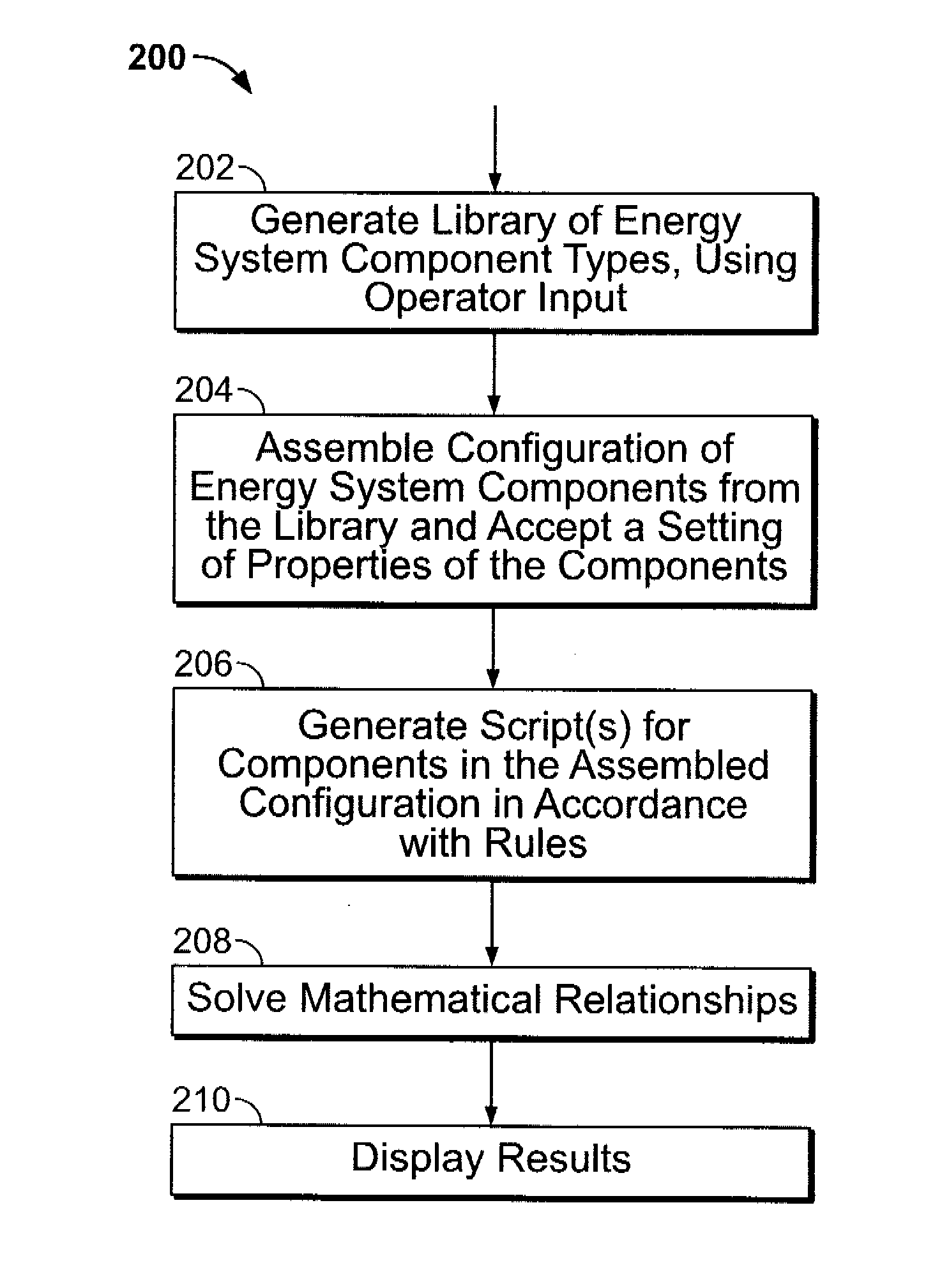
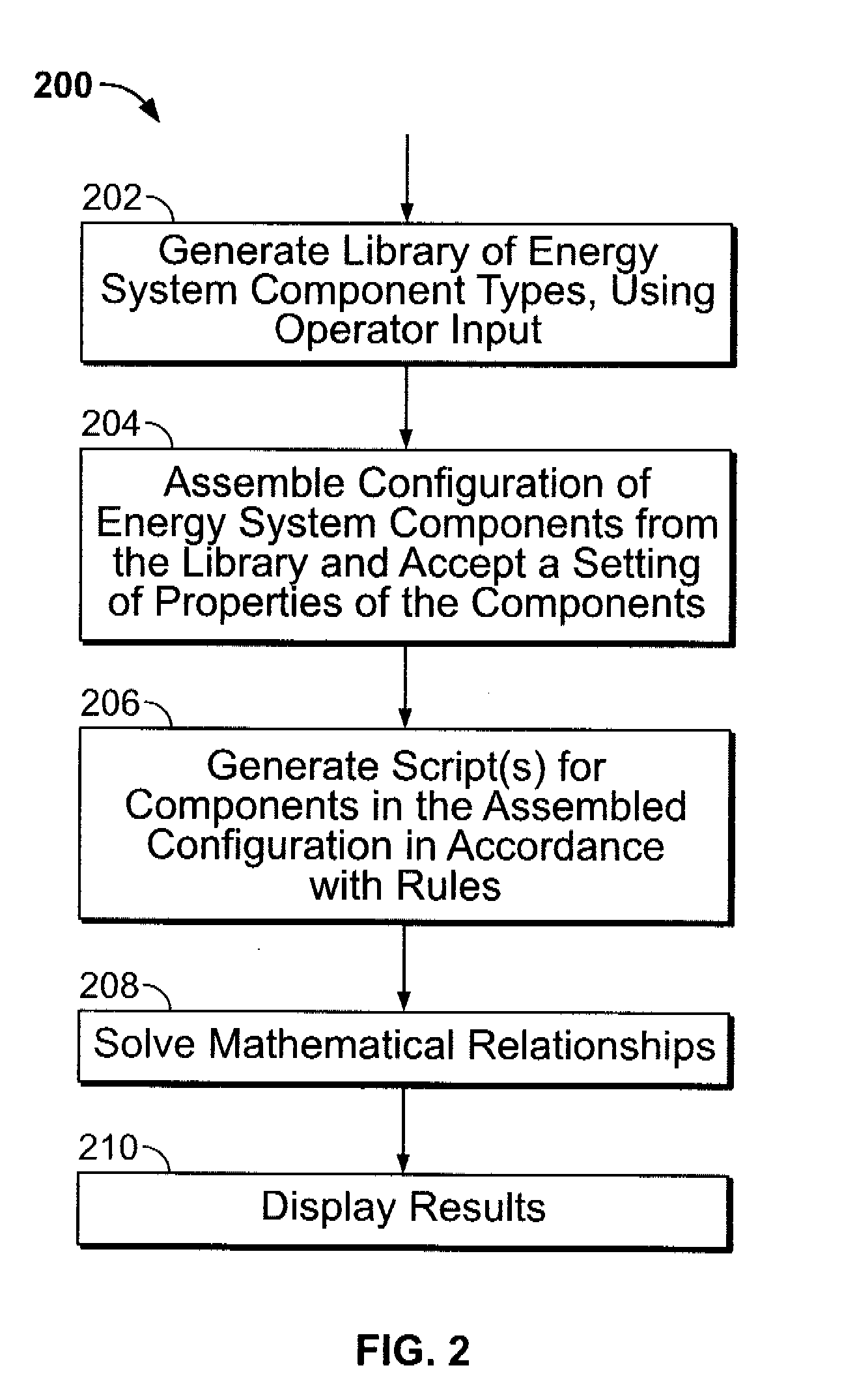
[0018] Some configurations of the present invention provide computer-implemented methods and apparatus for modeling energy systems. Technical effects of some configurations of the present invention include the generation and solution of energy system models that predict performance of an energy system under varying physical, operational, and / or economic conditions.

[0019] Some configurations of the present invention facilitate the creation of equipment definition files with configurable properties and the development of rules to govern behavior of equipment to produce optimal settings for one or more specific equipment types. Also, technical effects of various configurations of the present invention include, but are not limited to, facilitating the definition of new equipment types, properties, and rules that govern equipment behavior.

[0020] An optimization system in some configurations of the present invention combines an energy system model that predicts performance of the energy...


PUM


Abstract

A computer-implemented method for modeling and/or improving operational performance of an energy system includes providing a graphical user interface configured to allow a user to manipulate equipment icons into an energy system model representation, using modular, piece-wise linear equipment models to simulate non-linear behavior of equipment represented by the manipulated equipment icons to solve an energy system model represented by the manipulation, and displaying a solution of the energy system model.

Description

BACKGROUND OF THE INVENTION [0001] This invention relates generally to computer-implemented methods and apparatus for modeling energy systems. [0002] Profitable operation of an energy system is of particular interest in industry. Optimization of operation requires predictive models depicting thermo-economic performance of the energy system, and a method to solve those models in order to determine the most profitable way to operate the system. The performance of many of these energy systems is strongly influenced by various factors including environmental factors, operational factors or constraints (e.g. production limits and system output requirements). [0003] Energy systems vary in configuration of both equipment setup and processes. One known plant optimization software configuration described in U.S. Pat. No. 6,591,225, issued Jul. 8, 2003, has set a standard for efficient optimization of classical configurations of power plants. However, the structure of this software does not p...

Claims


Application Information

Patent Timeline
IPC IPC(8): G06G7/48
CPCG06F2217/78G06F17/50G06F30/00G06F2119/06
Inventor DAVARI, BIJANWILLIAMS, SCOTT TERRELLPECHTL, PETER ANTONMCDONALD, LARRY KEITHONG'IRO, ALFRED
Owner BAKER HUGHES INC
Why Eureka
Try Eureka