Exhaust gas purifying apparatus and method in internal combustion engine

a technology of exhaust gas purification apparatus and internal combustion engine, which is applied in mechanical equipment, machines/engines, electric control, etc., can solve the problems of engine output reduction, engine emissions risk, torque shock generation, etc., and achieve the effect of not deteriorating engine emissions

Inactive Publication Date: 2007-07-26
TOYOTA IND CORP +1
View PDF10 Cites 4 Cited by
  • Summary
  • Abstract
  • Description
  • Claims
  • Application Information

AI Technical Summary

Benefits of technology

[0005] The objective of the present invention is to regenerate a purifier without deteriorating engine emissions.
[0007] In accordance with another aspect of the present invention, an exhaust gas purifying method in an internal combustion engine having an intake path, first and second exhaust paths arranged in parallel, and an exhaust gas purifier provided at least in the first exhaust path, is provided. The method includes: supplying exhaust gas from the first exhaust path to the intake path through a first exhaust gas supply path; supplying exhaust gas from the second exhaust path to the intake path through a second exhaust gas supply path; causing the exhaust gas supplied to the intake path from the first exhaust path and the exhaust gas supplied to the intake path from the second exhaust path to merge; executing a process for regenerating the purifier; and reducing the flow rate of exhaust gas discharged from the first exhaust path and the flow rate of exhaust gas supplied to the intake path via the second exhaust gas supply path, when the process for regenerating the purifier is executed.

Problems solved by technology

However, in a case where the degree of opening of the exhaust throttle valve is simply lowered, engine output is reduced and torque shock is generated.
However, in order to reduce the exhaust flow rate, since it is necessary to reduce the amount of fresh air reaching the engine, there is a risk of a deterioration in engine emissions such as an increase in smoke.

Method used


Image

  • Exhaust gas purifying apparatus and method in internal combustion engine
  • Exhaust gas purifying apparatus and method in internal combustion engine
  • Exhaust gas purifying apparatus and method in internal combustion engine

Examples


first embodiment

[0018] A description will be given below of a first embodiment obtained by embodying the present invention in a diesel engine with reference to FIGS. 1A to 3.

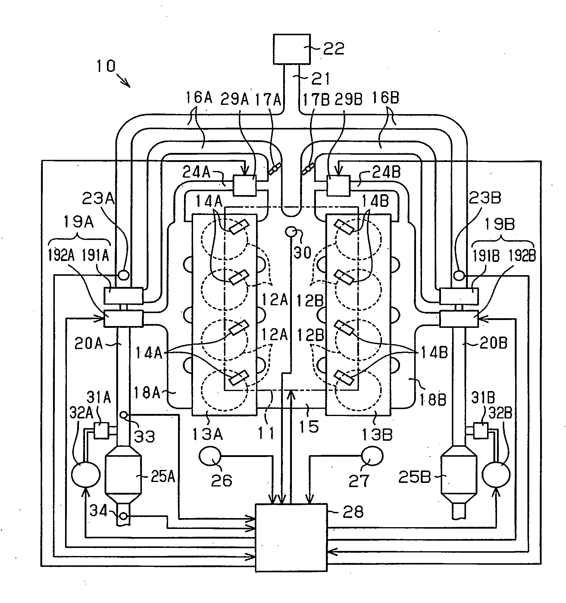
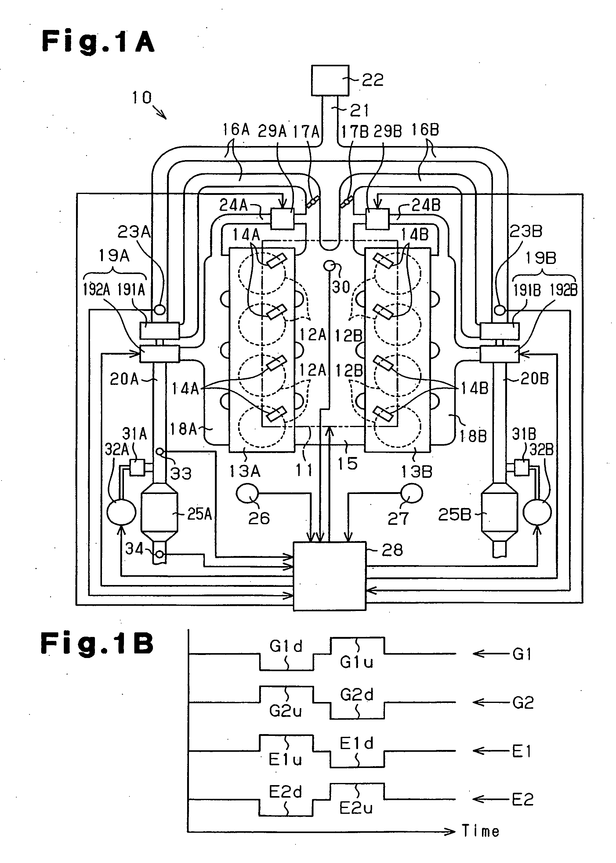
[0019] As shown in FIG. 1A, an internal combustion engine 10 mounted on a vehicle is provided with a plurality of cylinders 12A and 12B, and a plurality of cylinders 12A and 12B are separated into two groups. A cylinder head 13A is provided to correspond to one of the groups of the cylinders, or the cylinders 12A. A cylinder head 13B is provided to correspond to the other group of the cylinders, or the cylinders 12B. A fuel injection nozzle 14A is attached to each cylinder 12A, and a fuel injection nozzle 14B is attached to each cylinder 12B. The fuel injection nozzles 14A and 14B inject fuel into the respective cylinders 12A and 12B. Reference numeral 11 denotes a fuel injection apparatus that includes the fuel injection nozzles 14A and 14B.

[0020] An intake manifold 15 is connected to the cylinder heads 13A and 13B. Serving a...

third embodiment

[0080] A control computer 28E in the third embodiment controls valve opening degrees in the exhaust throttle valves 35A and 35B, and valve opening degrees in the flow rate adjusting valves 29A and 29B. The control computer 28E controls the valve opening degrees of the exhaust throttle valves 35A and 35B, for example, on the basis of brake pedal operation information obtained from a sensor for detecting the depression of a brake pedal (not shown).

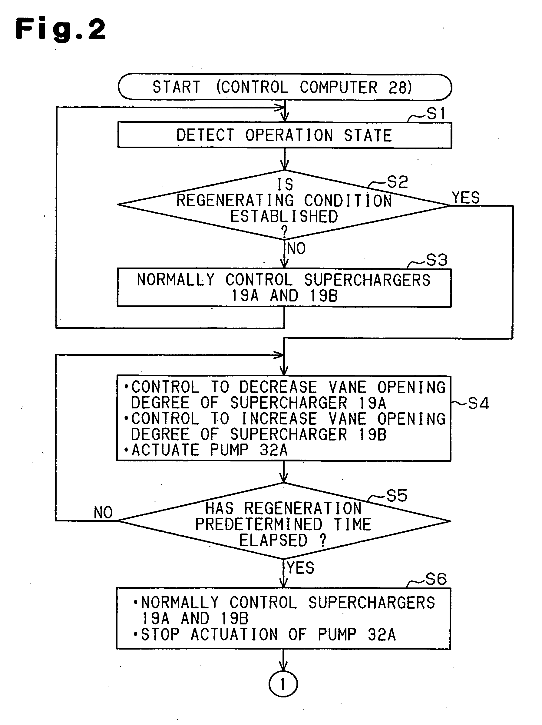
[0081] The control computer 28E executes the regeneration control program illustrated by flowcharts in FIGS. 6 and 7. A description will be given below of regeneration control on the basis of the flowcharts in FIGS. 6 and 7.

[0082] In cases where it has not executed regeneration, the control computer 28E loads an elapsed time Tx from an initial moving time of the engine in a predetermined control cycle and in cases where regeneration has already been executed, loads an elapsed time Tx from an end time of the preceding regeneration in a prede...


PUM


Abstract

When conditions for regenerating purifiers are established, a control computer first causes an addition nozzle to supply a reducing agent to a first exhaust path. At this time, the control computer reduces a vane opening degree in a first supercharger and increases a vane opening degree in a second supercharger. Accordingly, the flow rate of exhaust gas discharged to the outside from the first exhaust path is reduced, and the flow rate of exhaust gas flowing to the intake path via a first exhaust gas supply path is increased. Also, the flow rate of exhaust gas discharged to the outside from a second exhaust path is increased, and the flow rate of exhaust gas flowing to the intake path via a second exhaust gas supply path is reduced. As a result, the purifiers are regenerated in a reliable manner, while suppressing variations in the flow rate of exhaust gas supplied to the intake path.

Description

BACKGROUND OF THE INVENTION [0001] The present invention relates to an exhaust gas purifying apparatus and method in an internal combustion engine in which a plurality of exhaust paths are arranged in parallel, and purifiers purifying exhaust gas are respectively provided in the plurality of exhaust paths. [0002] An exhaust gas purifying apparatus has been conventionally utilized in which purification of exhaust gas is carried out by arranging a catalyst in the exhaust path of the engine. A part of equipment such as V-type engines employs a structure in which a plurality of exhaust paths are arranged in parallel. For example, an exhaust gas purifying apparatus in which a catalyst device is provided in each of a pair of exhaust paths arranged in parallel is disclosed in Japanese Laid-Open Patent Publication No. 50-13718 and Japanese Laid-Open Patent Publication No. 3-281929. [0003] In Japanese Laid-Open Patent Publication No. 11-294145 is disclosed an in-line four cylinder diesel eng...

Claims


Application Information

Patent Timeline
Patent Type & Authority Applications(United States)
IPC IPC(8): F02M25/07F02B47/08F02B33/44
CPCF01N3/0814F01N13/011F01N3/206F01N13/107F01N2410/04F01N2410/12F02B37/002F02B37/007F02B37/22F02D9/04F02D23/00F02D41/0007F02D41/0055F02D41/027F02D41/1445F02M25/0711F02M25/0713F02M25/0744F02M25/0749Y02T10/144Y02T10/47F01N3/0842F02M26/43F02M26/08F02M26/10F02M26/38Y02T10/12Y02T10/40
Inventor KAWAI, KENJISUZUKI, HISANOBU
Owner TOYOTA IND CORP
Why Eureka
Try Eureka