Filler tube assembly for a fuel vapor recirculation system

a technology of fuel vapor recirculation system and filler tube, which is applied in the direction of instruments, packaging goods types, applications, etc., can solve the problems of degradation of vapor storage medium, inconsistent vacuum conditions of filler tubes with tapered nozzle chambers

Inactive Publication Date: 2007-07-26
EATON CORP
View PDF9 Cites 20 Cited by
  • Summary
  • Abstract
  • Description
  • Claims
  • Application Information

AI Technical Summary

Benefits of technology

[0006] The present invention prevents liquid fuel from entering into the vapor recirculation line, which is tapped into the filler tube below the nozzle seal, when fuel rises in the filler tube when the tank is full. The invention includes a check valve having a flapper attached to the insert that is placed in the filler tube. The flapper is sensitive to fluid viscosity and distinguishes between liquid fuel and fuel vapor due to the inherently different viscosities of liquid and vapor. During use, the check valve response to the changes in viscosity of fuel surrounding the flapper as well as the differential pressure on either side of the flapper to open and close the vapor port.
[0007] The flapper of the present invention therefore closes when liquid fuel enters the upper end of the filler tube and opens in response to vapor pressure to allow proper vapor recirculation. By responding to both viscosity and differential pressure around the check valve, the check valve can distinguish between fuel vapor and liquid fuel in a simple yet reliable manner.

Problems solved by technology

Liquid fuel in the vapor vent system can block the vapor vent lines, trap fuel in low regions of the system or even cause degradation of the vapor storage medium in the vapor storage canister if fuel enters the canister.
Because the vacuum created in the filler tube depends on how much space is between the tip of the nozzle and the surrounding filler tube, filler tubes with a tapered nozzle chamber will generate inconsistent vacuum conditions because different nozzle lengths will end at different diameter portions of the nozzle chamber.

Method used


Image

  • Filler tube assembly for a fuel vapor recirculation system
  • Filler tube assembly for a fuel vapor recirculation system
  • Filler tube assembly for a fuel vapor recirculation system

Examples


Embodiment Construction

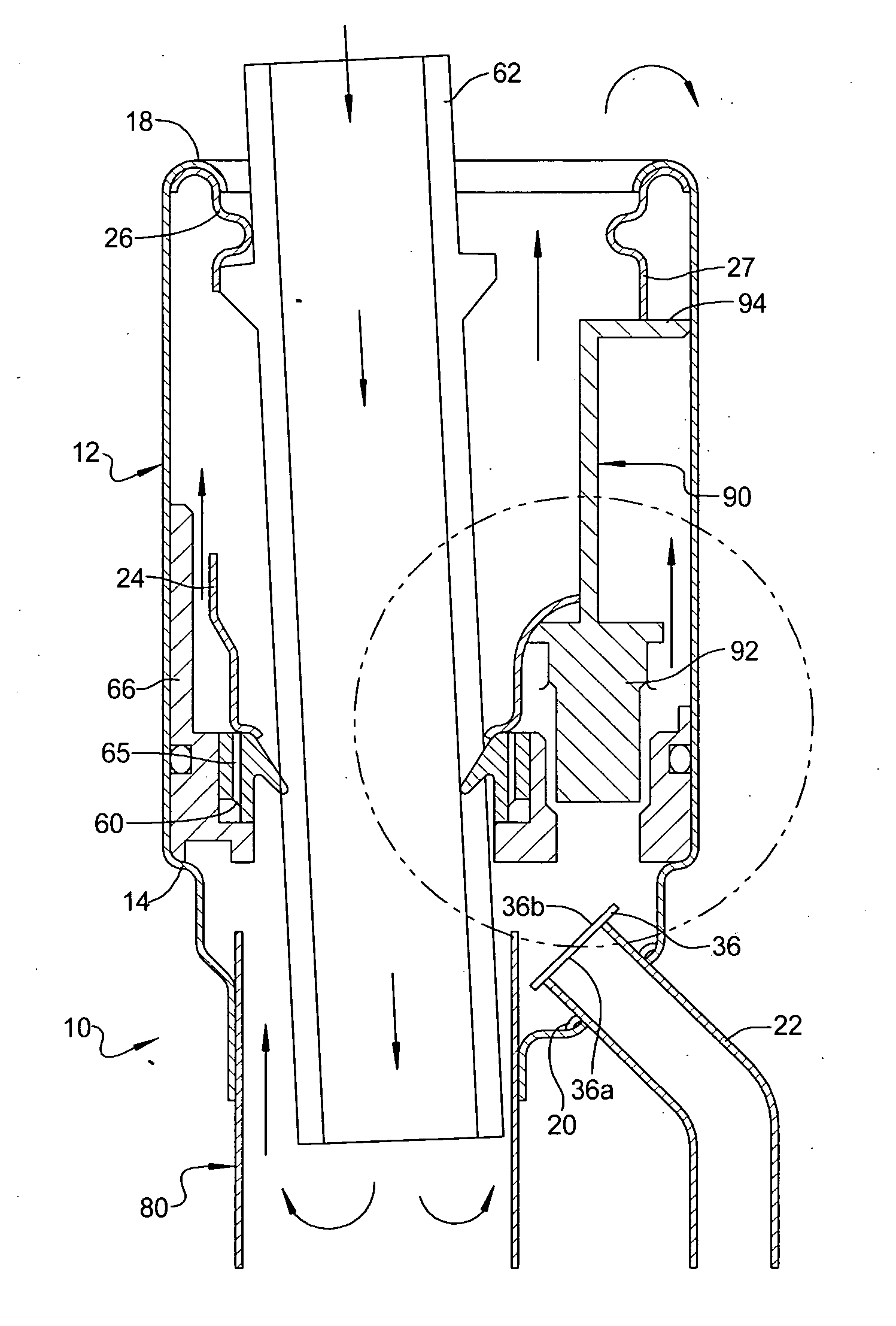
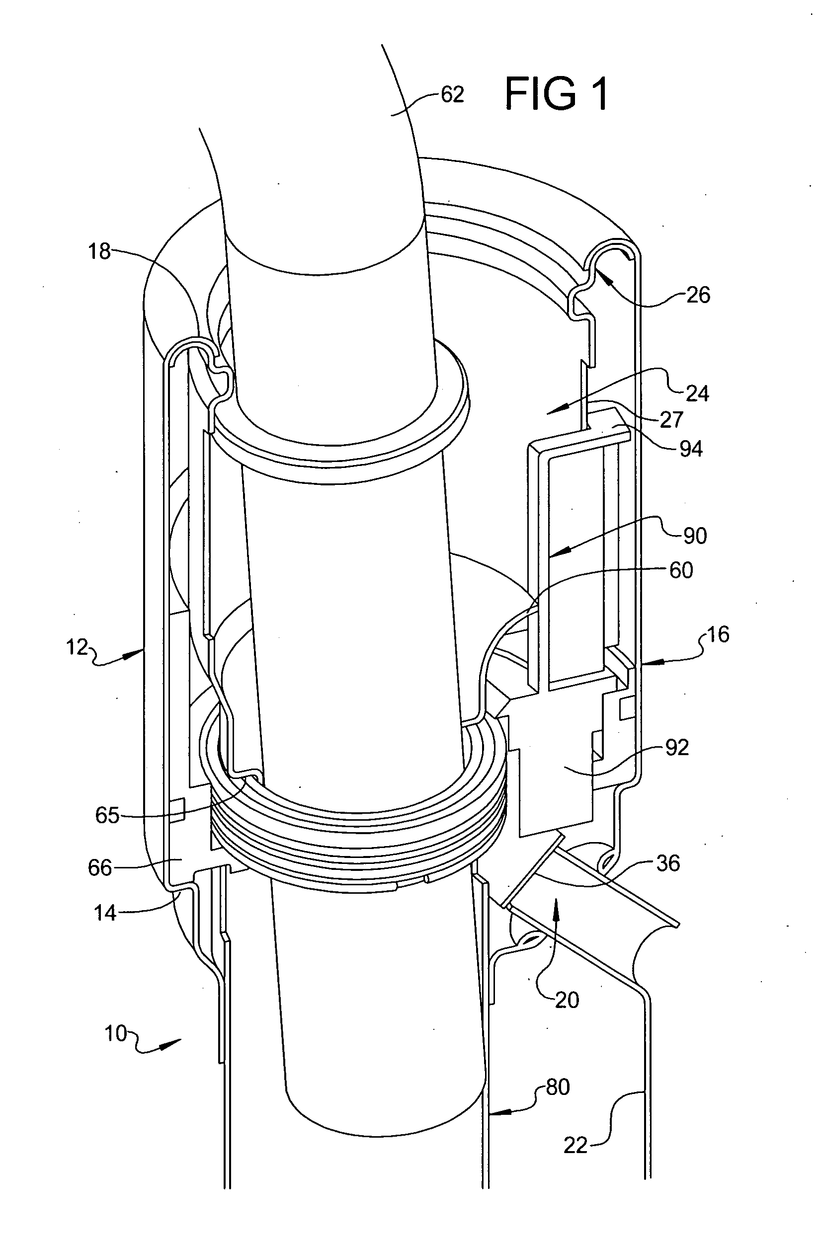
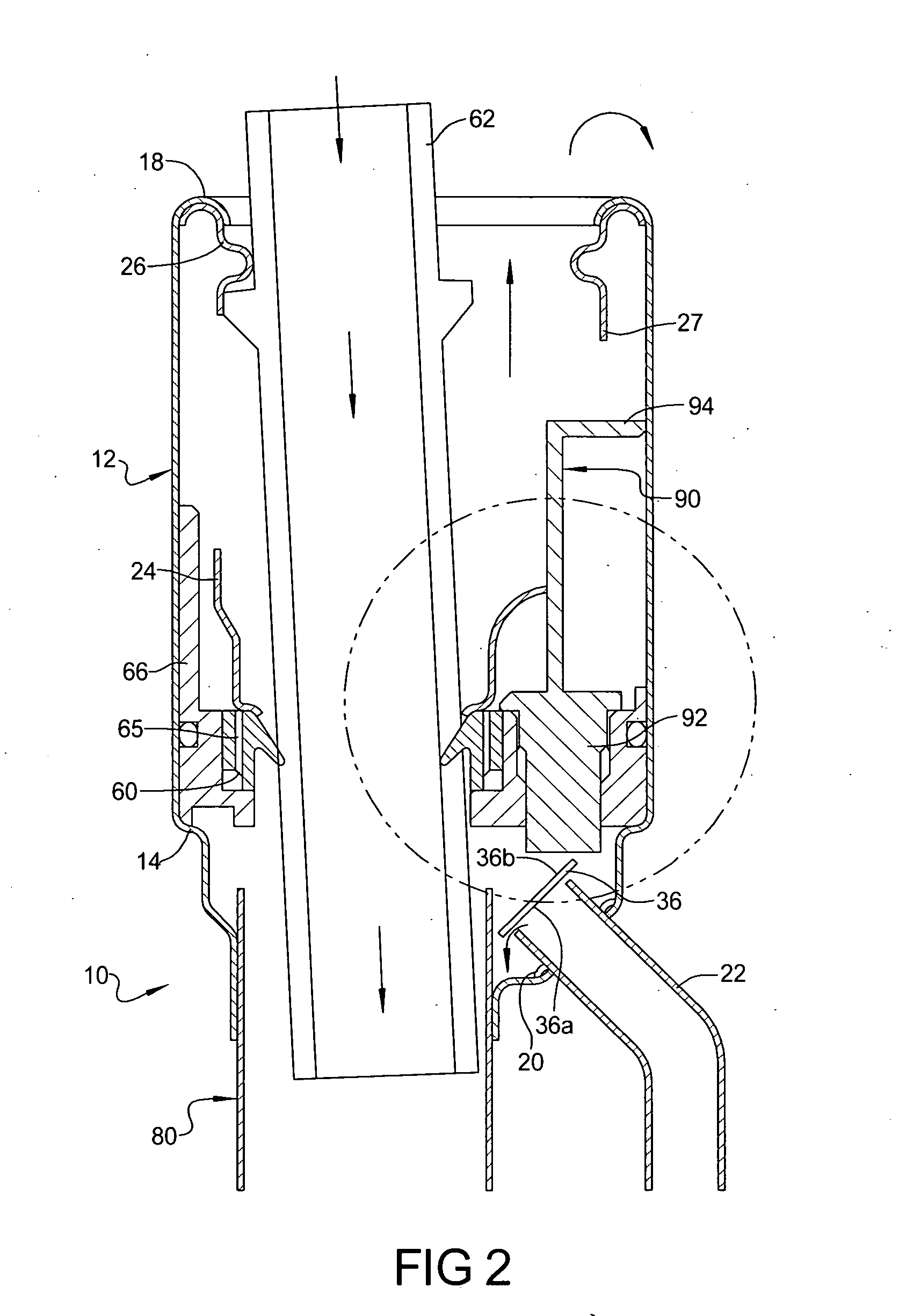
[0012] Referring to FIGS. 1 through 3, the inventive assembly includes a fuel tank filler tube 10 having an upper end 12. An annular step or shoulder 14 is formed on the tube 12. The step 14 transitions the tube 12 to an enlarged diameter portion 16 having an inwardly curling lip 18 formed at the upper end thereof. The tube 12 has a recirculation port or aperture 20 formed therein which is adapted for accommodating a recirculation tube 22 known in the fuel tank vapor system art.

[0013] A vapor check valve assembly 24 is disposed in the filler tube 10 and includes an annular flange 26 formed about an upper circumference of a cylinder 27. Upon installation of the assembly 24 in tube 16, the annular flange 26 engages the lip 18 of the tube portion 16 to maintain the insert against the shoulder 14. The check valve assembly 24 includes a flexible flapper 36 that can flex and move to open and close the recirculation port 20. In one embodiment, the flapper 36 is made of a material that is ...


PUM

PropertyMeasurementUnit
viscosityaaaaaaaaaa
diameteraaaaaaaaaa
flexibleaaaaaaaaaa

Abstract

A filler tube assembly for use in a system having vapor recirculation includes a check valve having a flapper that is responsive to the viscosity of fluid around the flapper and / or a differential pressure across the flapper. The assembly also includes a nozzle chamber formed in the filler neck that has a constant diameter to ensure consistent vacuum generation regardless of fuel nozzle length.

Description

TECHNICAL FIELD [0001] The present invention relates to filler tube assemblies for fuel tank installations having a fuel vapor recirculation tube ported to the upper end of the filler tube in an enlarged nozzle receiving end. BACKGROUND OF THE INVENTION [0002] Fuel vapor recirculation tubes are used in motor vehicle fuel tank filler tubes to recirculate fuel vapor during refueling from a nozzle inserted in the filler tube with a mechanical seal provided about the nozzle. The recirculated vapor provides a make-up flow below the nozzle seal to prevent the flow discharging from the nozzle from creating a vacuum in the filler tube and prematurely activating the automatic nozzle shutoff. [0003] Known fuel tank filler tube installations having a vapor recirculation tube attached to a port in the filler tube below the nozzle seal. This configuration sometimes allows liquid fuel to enter the vapor recirculation tube and flow into the vapor vent system when liquid fuel rises in the filler tu...

Claims


Application Information

Patent Timeline
Patent Type & Authority Applications(United States)
IPC IPC(8): B65B1/04B67D7/54B67D7/44
CPCF02M37/0082A47B65/00G10G7/00
Inventor BENJEY, ROBERT P.PIFER, DANIEL L.JAHNKE, RUSSELL C.
Owner EATON CORP
Why Eureka
Try Eureka