Convertible aircraft operating method

a technology operating method, which is applied in the direction of aircraft, rotorcraft, vehicles, etc., can solve the problems of limiting the maximum speed of rotary wing aircraft (gyroplanes and helicopters) to slightly over 350 km/h, and affecting the flight speed of rotary wing machines

Inactive Publication Date: 2007-07-26
GLAXO GROUP LTD +1
View PDF9 Cites 48 Cited by
  • Summary
  • Abstract
  • Description
  • Claims
  • Application Information

AI Technical Summary

Problems solved by technology

The efforts to achieve high flight speeds in rotary wing machines have been hindered by the basic fact that a rotor in flight, at relatively high speeds, exhibits a very asymmetric profile in the lift generated by the rotor blade when it “moves forward” in the wind produced by the aircraft's forward flight and when it “moves backward” in that same wind, the opposite side of the rotor disc.
Therefore, when a rotary wing aircraft attempts to fly at high speeds, it is possible that the tip of the blade exceeds the speed of sound on the blade that moves forward and / or suffers losses on the blade which moves backward, which leads to highly undesirable effects in the rotor's behaviour.
This factor has limited the maximum speed of rotary wing aircrafts (gyroplanes and helicopters) to slightly over 350 km / h.
Numerous military aeroplanes and some civil ones (such as the “Concorde”) reach supersonic speeds, but at the expense of substantial increases in consumption, noise. heating of the fuselage and several other characteristics.
The limited maximum speed of rotary wing aircrafts presents serious restrictions for the use thereof.
But many of the civil or military missions wherein helicopters are involved consist of transporting persons and / or cargo between two points, one or both of which may not be equipped with take-off or landing infrastructures.
In these cases, the low maximum and cruise velocities of gyroplanes and helicopters lead to long transport times, which greatly limits their practical use for many missions.
The prototype has as yet not reached sufficient velocity to be tested.

Method used


Image

  • Convertible aircraft operating method
  • Convertible aircraft operating method
  • Convertible aircraft operating method

Examples


Embodiment Construction

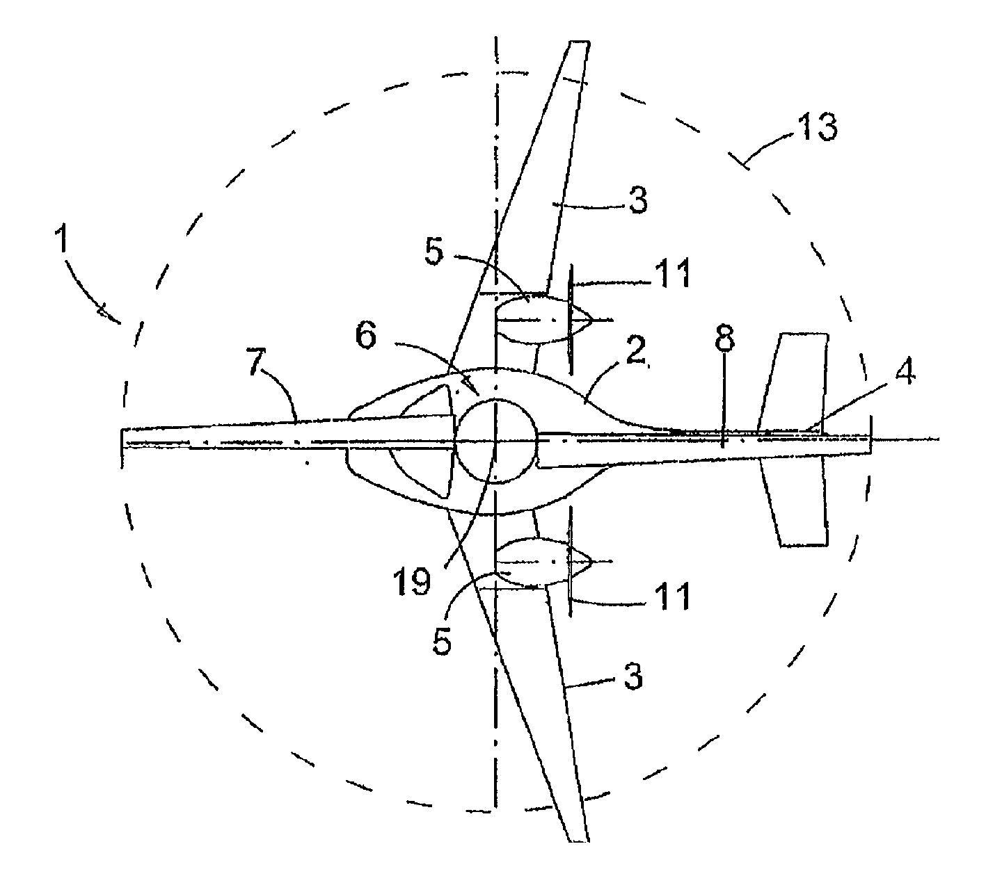
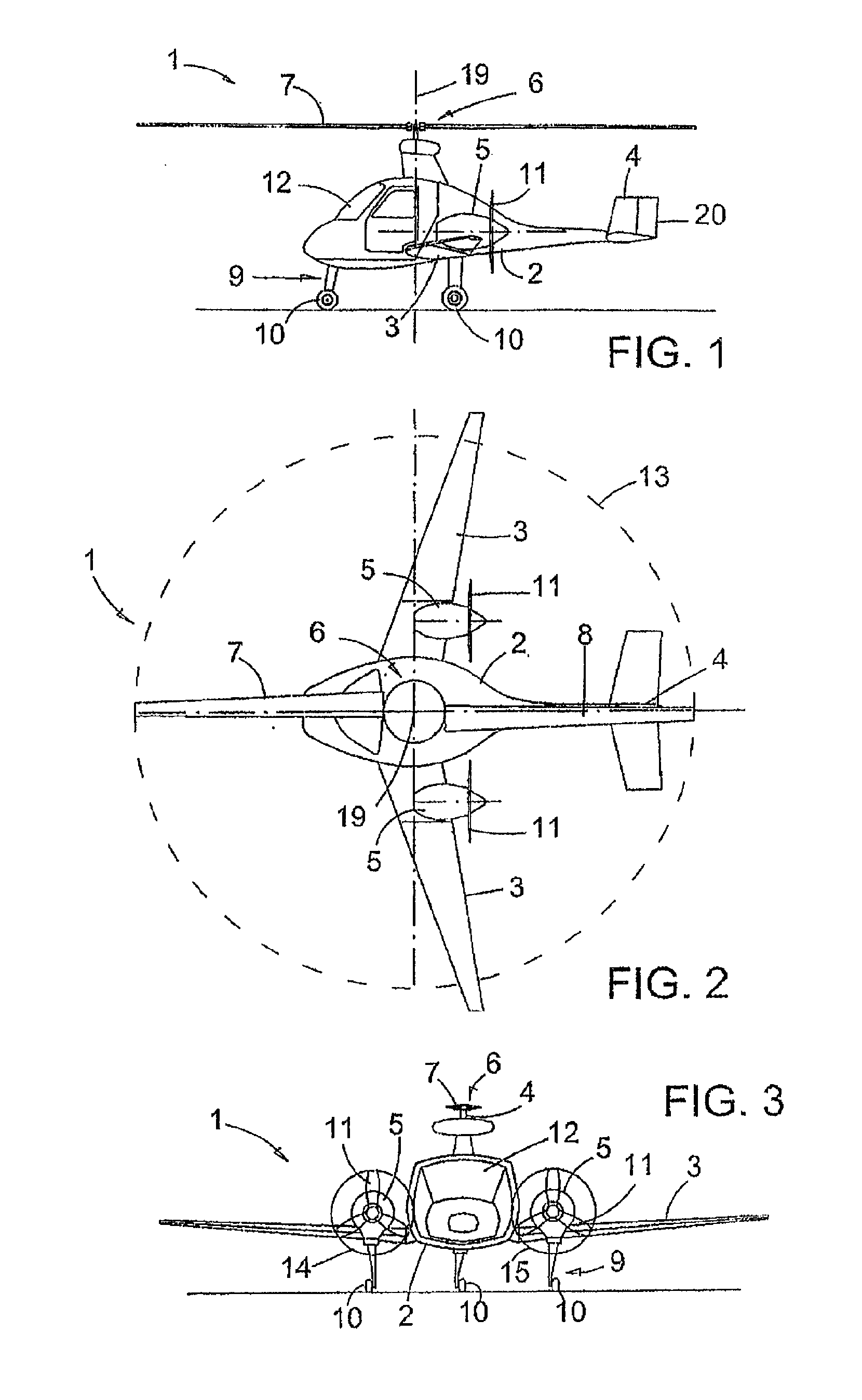
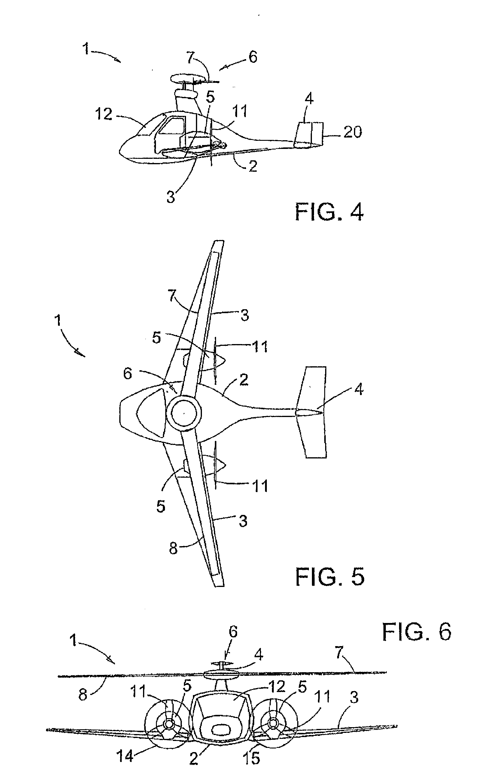
[0029] To this end, in one respect, the purpose of the invention is a new operating method for convertible aircrafts of the type indicated at the beginning, which, in essence, is characterised in that the method comprises a direct and reverse transition from helicopter mode to gyroplane mode and a direct and reverse transition from gyroplane-helicopter mode to aeroplane mode, the direct transition from helicopter mode to gyroplane mode comprising the following stages:

[0030] disengaging the clutch of the rotor from the rotor's propulsion engines, and the direct transition from gyroplane-helicopter mode to aeroplane mode comprising the following stages:

[0031] adjusting the collective and cyclic pitches of the rotor blades to essentially zero degrees, in such a way that they cease to lift and control the aircraft and the latter is lifted and controlled by the ailerons and the rudders;

[0032] quickly reducing the rotor's rotational velocity using the brake thereof;

[0033] stopping the...


PUM


Abstract

The invention relates to a convertible aircraft operating method. According to the invention, the aircraft comprises: a fuselage, standard fixed wings which are equipped with ailerons, a tail unit with flight-control surfaces, engines, a rotor with blades, a transmission which is placed between the engines and the rotor and which is equipped with rotor clutch and braking means, a landing gear, means for transition from helicopter mode to gyroplane mode and vice versa, and means for direct or reverse transition from gyroplane/helicopter mode to aeroplane mode. The lift for a range of low speeds is produced by means of the rotor, while the lift for a range of high speeds is produced by means of the wings. In addition, the lift for a range of intermediate speeds can be produced using the wings and the rotor in gyroplane mode simultaneously, and take-off and landing can be performed in gyroplane mode or in helicopter mode with the engines coupled to the rotor. The aircraft comprises a hybrid helicopter/gyroplane/aeroplane aircraft and, as such, can perform the direct or reverse transition to aeroplane mode from both helicopter mode and gyroplane mode.

Description

TECHNICAL FIELD OF THE INVENTION [0001] The invention generically relates to convertible aircrafts, of the type which comprise a fuselage, standard fixed wings equipped with ailerons, a tail unit with rudders, propulsion engines, a rotor with blades, a transmission between the engines and the rotor, equipped with braking and rotor clutch means, a landing gear and means for transition from helicopter mode to gyroplane mode and vice versa. [0002] The purpose of the invention is an operating method for a convertible aircraft which comprises a transition from helicopter mode to gyroplane mode and vice versa, as well as the convertible aircraft that uses said method. BACKGROUND OF THE INVENTION [0003] U.S. Pat. No. 1,590,497 and U.S. Pat. No. 1,947,901, by Juan de la Cierva y Codorniu, amongst others. define and protect the gyroplane, which is a machine equipped with rotary wings that obtains its main lift in flight from the reaction of air on a system of aerofoils or rotors capable of r...

Claims


Application Information

Patent Timeline
Patent Type & Authority Applications(United States)
IPC IPC(8): B64C27/26B64C27/02B64C27/24
CPCB64C27/26B64C27/24B64C27/026
Inventor DE LA CIERVA HOCES, JUAN
Owner GLAXO GROUP LTD
Why Eureka
Try Eureka