Driver and method for driving a semiconductor light emitting device array

a technology of light emitting devices and drivers, which is applied in the direction of electric variable regulation, process and machine control, instruments, etc., can solve the problems of failure to further support advanced functions such as dynamic contrast adjustment, scanning backlight, and color sequence facility for lcd, and achieve better lcd quality, better color gamut quality, and mitigate image blur

Active Publication Date: 2007-07-26
AU OPTRONICS CORP
View PDF11 Cites 47 Cited by
  • Summary
  • Abstract
  • Description
  • Claims
  • Application Information

AI Technical Summary

Benefits of technology

[0011] It is yet another object of the present invention to provide a current driver for driving an LED array, which is employed as a backlight module for a display device such as an LCD, and achieving better color gamut quality for the driven LED array.
[0012] It is still another object of the present invention to provide a current driver for driving an LED array, which is employed as a backlight module for a display device such as an LCD, and independently controlling the current flowing through the LED sets with different primary colors in an LED array so as to control the local color temperature.
[0013] It is yet another object of the present invention to provide an LED current driver capable of accepting image control signals from an application specific integrated circuit (ASIC) so as to independently control the luminance of each individual region in an LED array module, thus a dynamic contrast function can be implemented to achieve a better LCD quality.
[0014] It is yet another object of the present invention to provide an LED current driver capable of accepting image control signals from an ASIC so as to independently control on-off timing of each individual region in an LED array module, thus a scanning backlight facility can be achieved to mitigate image blur effect and enhance the contrast.
[0015] It is yet another object of the present invention to provide an LED current driver capable of accepting image control signals from an ASIC so as to independently control the on-off timing or frequency of LED sets with different primary colors in an LED array module, thus a color sequence facility can be achieved and the necessity of using color filters may be reduced.
[0016] The modularized LED drivers according to one embodiment of the present invention, for example, may be jointly applied to the backlight of a large dimension LCD. The LED driver of the present invention controls the luminance, on-off timing, duty cycle, and frequency of each LED set in an LED array module by using feedback, compensation, as well as regulation techniques. The mechanism disclosed in the present invention will enable a display device, such as an LCD, to accomplish a lot of desired image processing functions. Moreover, the present invention employs active elements and thus can provide faster, stabler, and more accurate dynamic response. The driver in accordance with the present invention includes at least one current regulator unit having a plurality of controllable switches to regulate the current of each set of cascaded light emitting devices in the semiconductor light emitting device array. The currents of the sets are used to generate a plurality of feedback signals through a feedback unit. A compensation unit generates a plurality of control signals in response to the feedback signals and a plurality of timing signals, so as to control the controllable switches.

Problems solved by technology

These conventional driving mechanisms, however, can only achieve a current stability of the entire LED array and the color temperature adjustment in a global sense.
Such conventional driving methods still restrain an LED array backlight module from achieving further functions such as dynamic contrast, scanning backlight, and color sequence facility.
The mechanism, however, can only attain global current stability and color temperature of the LED array, but fails to further support advanced functions such as the dynamic contrast adjustment, scanning backlight, and the color sequence facility for the LCD.
This patent focuses on monitoring the total current flowing through the entire LED array, and still fails to attain above advantages when the LED array is employed as a display backlight module.

Method used


Image

  • Driver and method for driving a semiconductor light emitting device array
  • Driver and method for driving a semiconductor light emitting device array
  • Driver and method for driving a semiconductor light emitting device array

Examples


Embodiment Construction

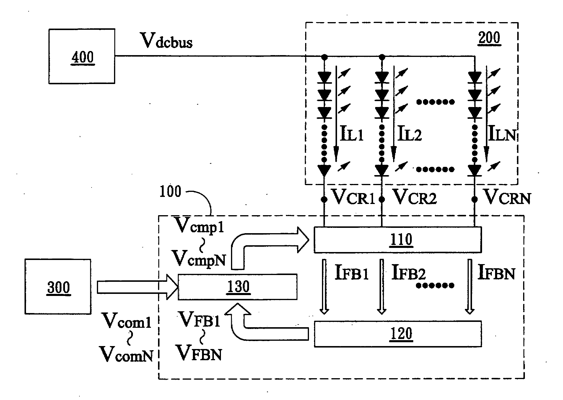
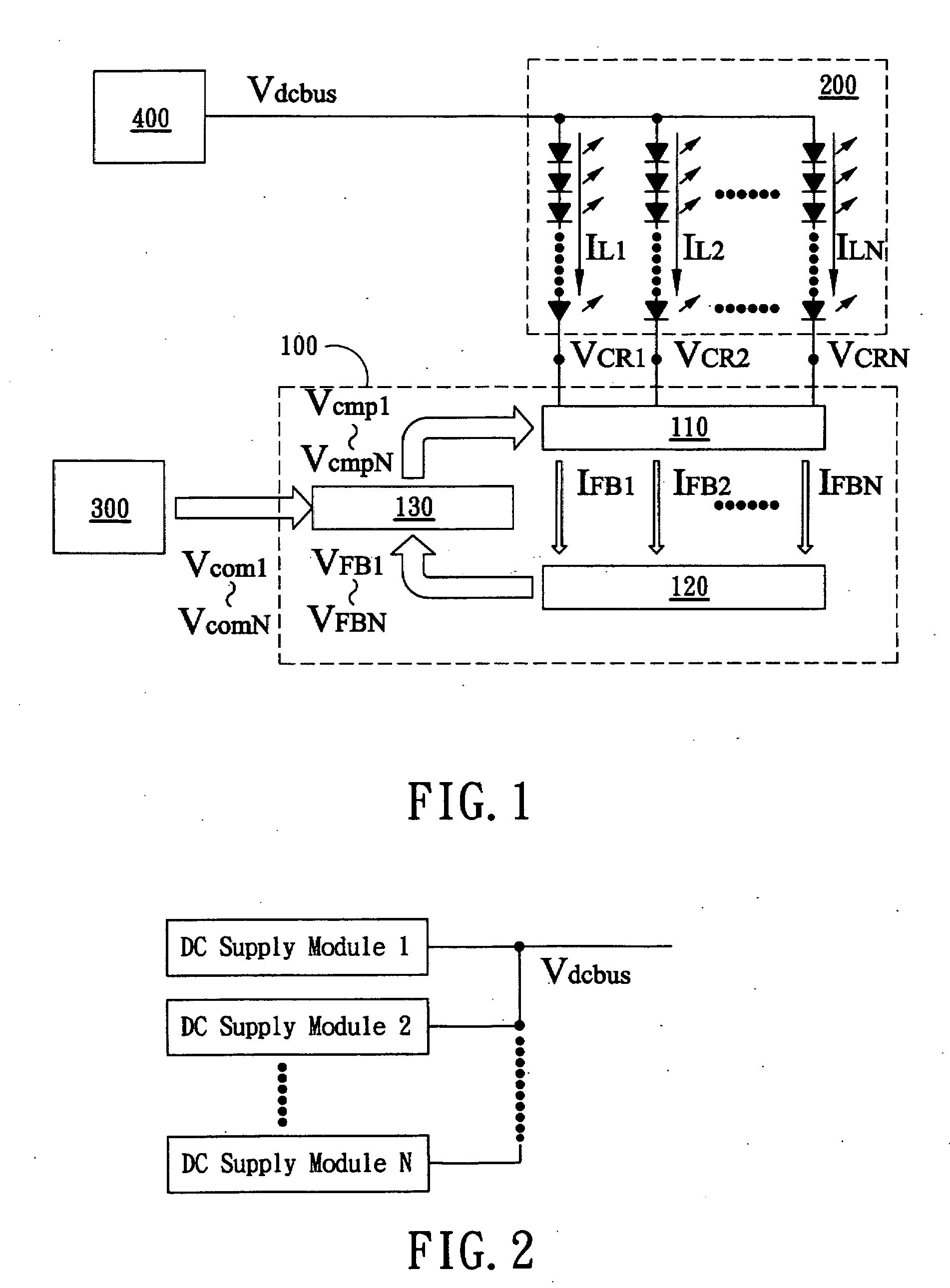
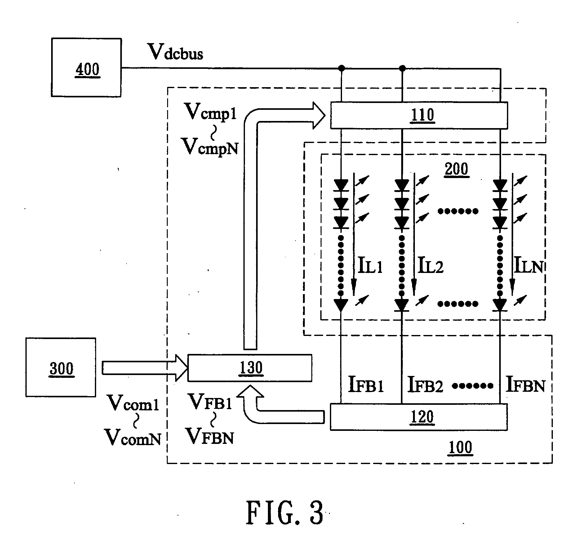
[0027]FIG. 1 shows a block diagram of a preferred embodiment of the active current driver of a semiconductor light emitting device array according to the present invention. Although light emitting diodes (LEDs) are used in the present embodiment, other light emitting devices may be adaptable. In the present embodiment, the active current driver is utilized to drive an LED array module 200. The active current driver includes an LED active current regulator module 100, a timing control module 300, and a DC supply module 400, in which the LED active current regulator module 100 includes a current regulator unit 110, a feedback unit 120, and a compensation unit 130.

[0028] As shown in the figure, the DC supply module 400 is electrically connected to the LED array module 200; the LED array module 200 is connected to the current regulator unit 110; and the timing control module 300 is connected to the compensation unit 130. In the LED active current regulator module 100, the current regul...


PUM


Abstract

A driver and method for driving a semiconductor light emitting device array is provided. The driver includes at least one current regulator unit having a plurality of controllable switches to regulate the current of each set of cascaded light emitting devices in the semiconductor light emitting device array. The currents of the sets are used to generate a plurality of feedback signals through a feedback unit. A compensation unit generates a plurality of control signals in response to the feedback signals and a plurality of timing signals, so as to control the controllable switches. A driver according to the present invention can independently and individually control the luminance and timing of each set of cascaded light emitting devices.

Description

BACKGROUND OF THE INVENTION [0001] 1. Field of the Invention [0002] The present invention relates to a driver and method for driving a semiconductor light emitting device array, and more particularly to a driver and method for driving a light emitting diode (LED) array supporting dynamic image control functions. [0003] 2. Description of the Prior Art [0004] Light emitting diode (LED) arrays have been gradually employed as the backlight module to a liquid crystal display (LCD). Compared with conventional cold cathode fluorescent lamp (CCFL) backlight modules, the LED arrays are preferable in environmental protection consideration and color brightness performance. The LED backlight module, such as a small size white LED backlight, is generally driven by a constant current controlled by a DC voltage. Another driving type is to use a current sink integrated circuit (IC) to regulate the current flowing through the LEDs of distinct primary colors (that is, red, green, and blue). These con...

Claims


Application Information

Patent Timeline
Patent Type & Authority Applications(United States)
IPC IPC(8): B41J2/435
CPCH05B33/086H05B33/0827H05B45/20H05B45/46
Inventor WEY, CHINDERYEH, YI-CHUNSUN, CHIA-HUNGLEE, TSUNG-SHIUN
Owner AU OPTRONICS CORP
Why Eureka
Try Eureka