Control circuit including adaptive bias for transformer voltage detection of a power converter

a control circuit and transformer technology, applied in the field of power converters, can solve the problems of inability to accurately measure the flyback voltage and light load condition, and achieve the effect of facilitating the detection of flyback voltage and preventing waveform distortion

Active Publication Date:
View PDF9 Cites 9 Cited by
  • Summary
  • Abstract
  • Description
  • Claims
  • Application Information

AI Technical Summary

Benefits of technology

[0007] A control circuit is developed to detect the flyback voltage of a transformer of the power converter and regulate the output of the power converter. The control circuit comprises a switch and a controller, in which the switch is coupled to the transformer to switch the transformer and transfer the energy from the primary side to the secondary side of the transform. The controller includes a detection circuit, a switching circuit and an adjust circuit. The detection circuit is coupled to the transformer to detect the flyback voltage of the transformer for generating a first signal and a second signal in accordance with the flyback voltage. The first signal is correlated to the output of the power converter. The second signal represents the discharge time of the transformer. The switching circuit is used for generating a control signal to control the switch and regulate the output of the power converter in response to the first signal. The adjust circuit is utilized to generate an adjust signal in response to the pulse width of the second signal. The detection circuit generates a bias signal transmitted to a voltage-detection terminal of the detection circuit to help the flyback voltage detection and prevent the waveform distortion. The bias signal is produced in proportional to the adjust signal. Besides, the switching circuit generates a blanking signal in response to the control signal. The blanking signal ensures a minimum on time of the control signal once the control signal is switched on. The minimum on time of the control signal produces a minimum pulse width of the flyback voltage, which further facilitates the flyback voltage detection.

Problems solved by technology

A flyback control technique has been disclosed in U.S. Pat. No. 4,302,803 “Rectifier-Converter Power Supply with Multi-Channel Flyback Inverter”, issued to Randolph D. W. Shelly. However, the disadvantage of the foregoing prior art is the flyback voltage cannot be accurately measured, particularly at the light load condition. FIG. 2 shows the waveforms of the power converter at light load.

Method used


Image

  • Control circuit including adaptive bias for transformer voltage detection of a power converter
  • Control circuit including adaptive bias for transformer voltage detection of a power converter
  • Control circuit including adaptive bias for transformer voltage detection of a power converter

Examples


Embodiment Construction

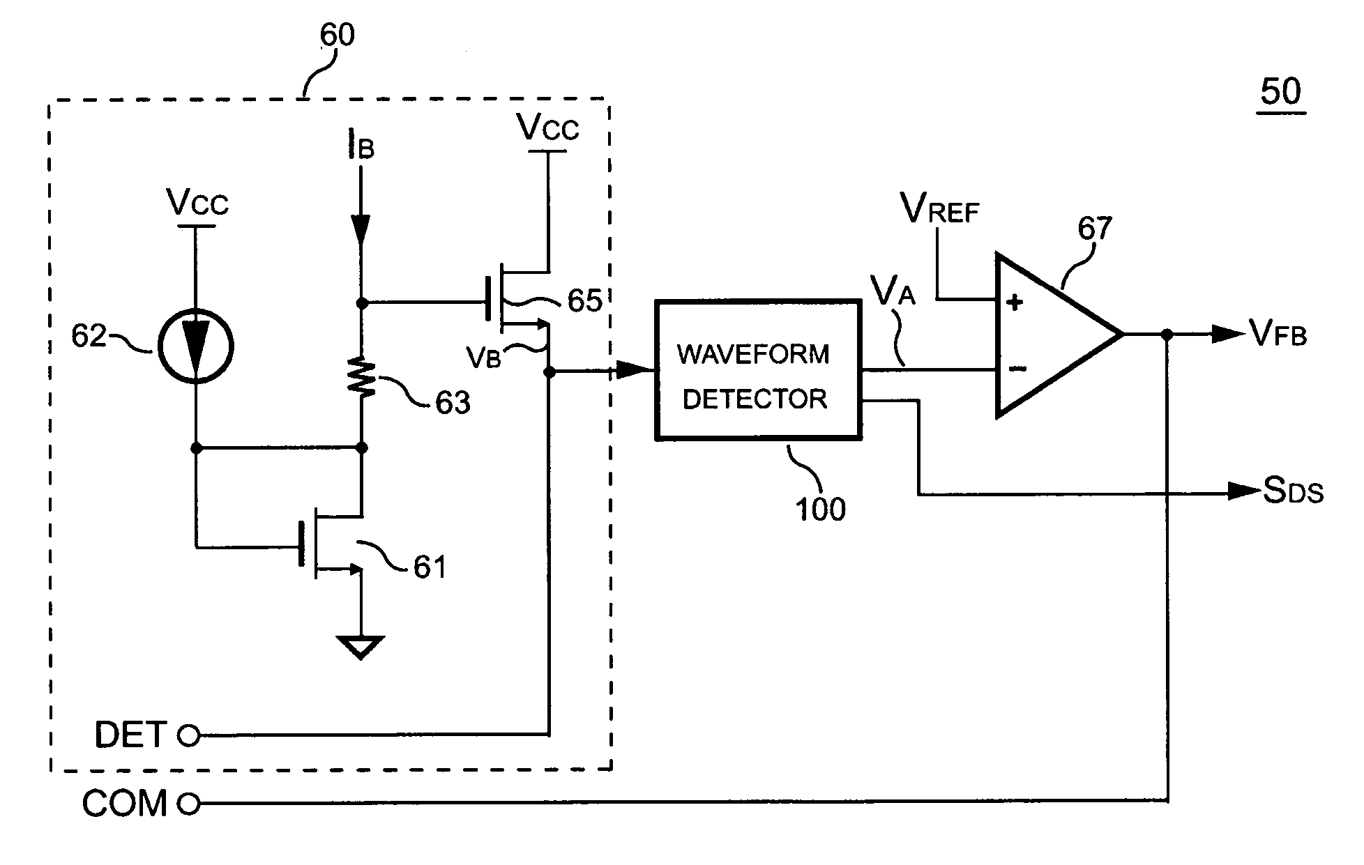
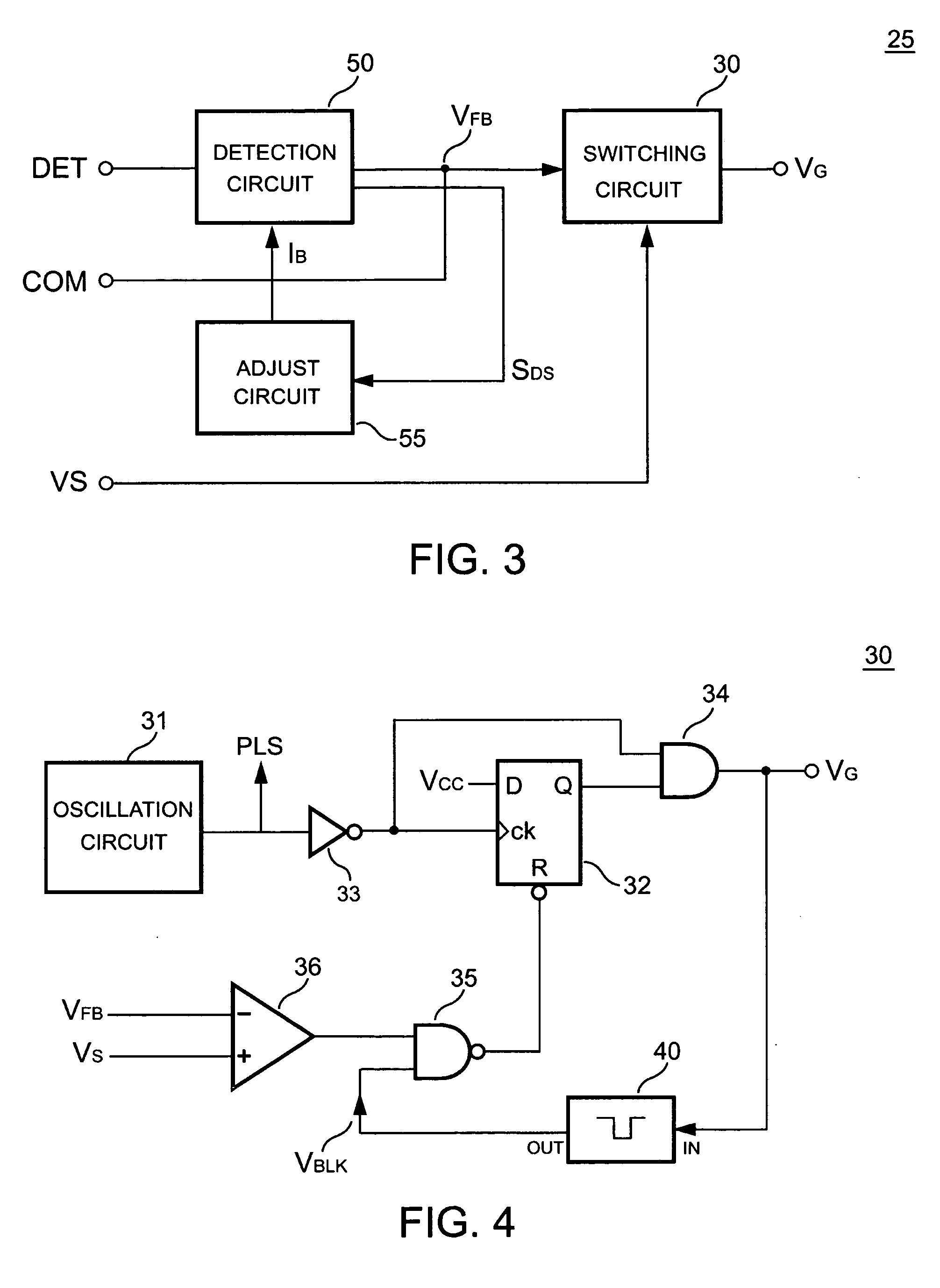
[0019] The control circuit of the power converter comprises the switch 20 and the controller 25. The controller 25 generates a control signal VG to control the switch 20 for switching the transformer 10. FIG. 3 shows a block diagram of the controller 25 according to one embodiment of the present invention. The controller 25 includes a switching circuit 30, a detection circuit 50 and an adjust circuit 55. The detection circuit 50 is coupled to the transformer 10 to detect the flyback voltage VF of the transformer 10 through the voltage-detection terminal DET for generating a first signal VFB and a second signal SDS in accordance with the flyback voltage VF. The first signal VFB is correlated to the output voltage VO of the power converter. The second signal SDS represents the discharge time TDS of the transformer 10. The first signal VFB is transmitted to the compensation terminal COM. The switching circuit 30 generates a control signal VG to control the switch 20 and regulate the ou...


PUM


Abstract

A control circuit is developed to detect a flyback voltage of a transformer of a power converter. The control circuit comprises a switch, a detection circuit and a switching circuit. The switch is coupled to the transformer for switching the transformer. The detection circuit coupled the transformer to detect the flyback voltage for generating a first signal. The switching circuit generates a control signal to control the switch and regulate the output of the power converter in response to the first signal. Because the pulse width of the flyback voltage is short at light load, the detection circuit is designed to produce a bias signal to help the flyback voltage detection. The bias signal is increased in response to the decrease of the discharge time of the transformer. Besides, the switching circuit generates a blanking signal in response to the control signal. The blanking signal ensures a minimum pulse width of the flyback voltage.

Description

BACKGROUND OF THE INVENTION [0001] 1. Field of the Invention [0002] The present invention relates to a power converter, and more specifically relates to a control circuit of the switching power converter. [0003] 2. Description of Related Art [0004] Power converters have been widely used for providing regulated outputs. For safety, the power converter must provide the isolation between its primary side and secondary side. A transformer is usually equipped to provide the isolation and the energy transfer. FIG. 1 shows a power converter having a transformer 10. The energy is stored into the transformer 10 during a switch 20 is on, in which the switch 20 is a power transistor or a power MOSFET. The energy will be discharged to the output of the power converter when the switch 20 is switched off. A current-sense resistor 21 is connected in series with the switch 20 to sense the switching current of the transformer 10 and generate a current signal VS for the switching control. A voltage-d...

Claims


Application Information

Patent Timeline
Patent Type & Authority Applications(United States)
IPC IPC(8): H02M3/335
CPCH02M3/33507
Inventor YANG, TA-YUNG
Why Eureka
Try Eureka