

Optical recording/reproducing apparatus, optical pickup, and tracking error detecting method
- Summary
- Abstract
- Description
- Claims
- Application Information
AI Technical Summary
Benefits of technology
Problems solved by technology
Method used
Image

Examples
second embodiment
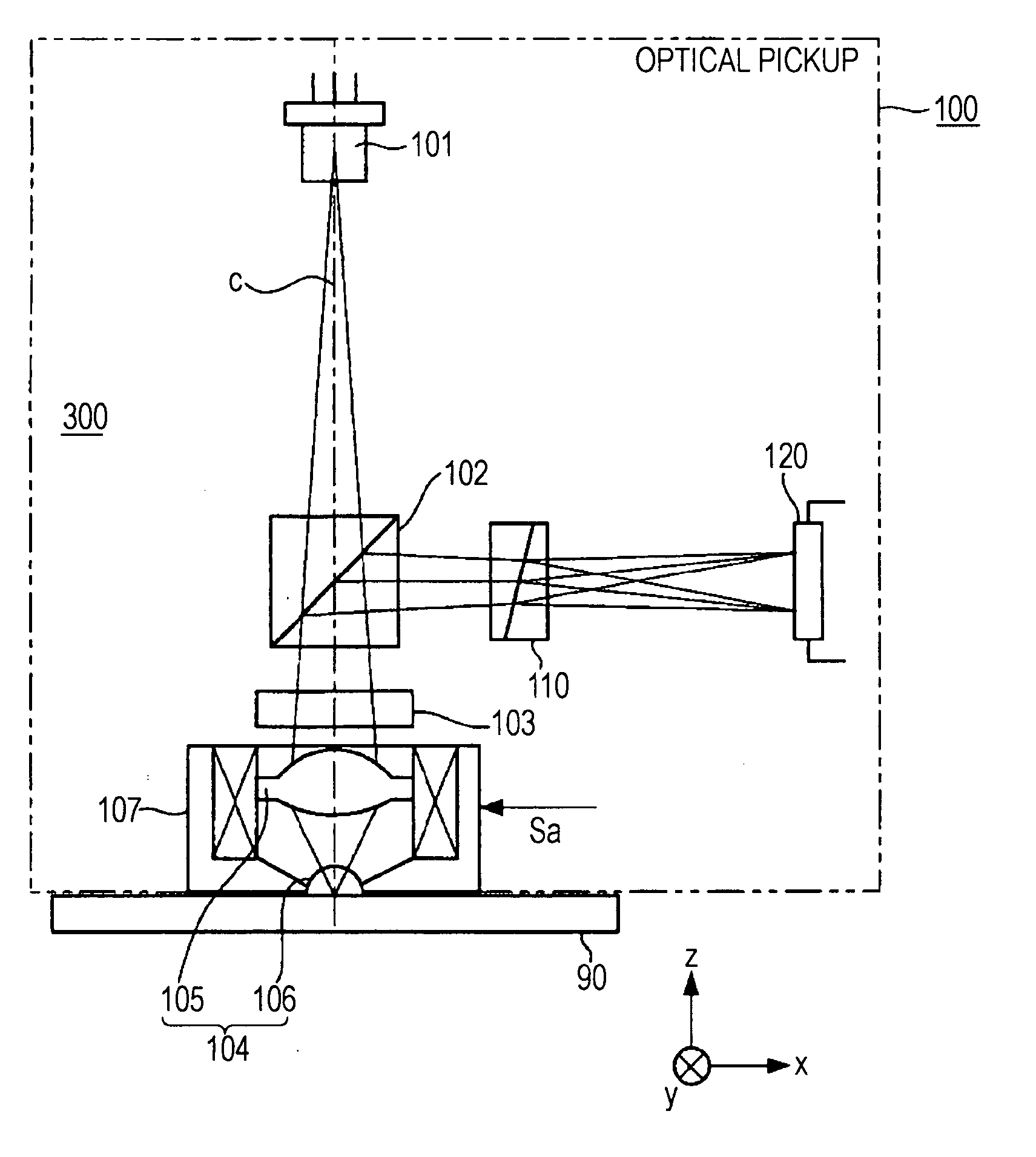
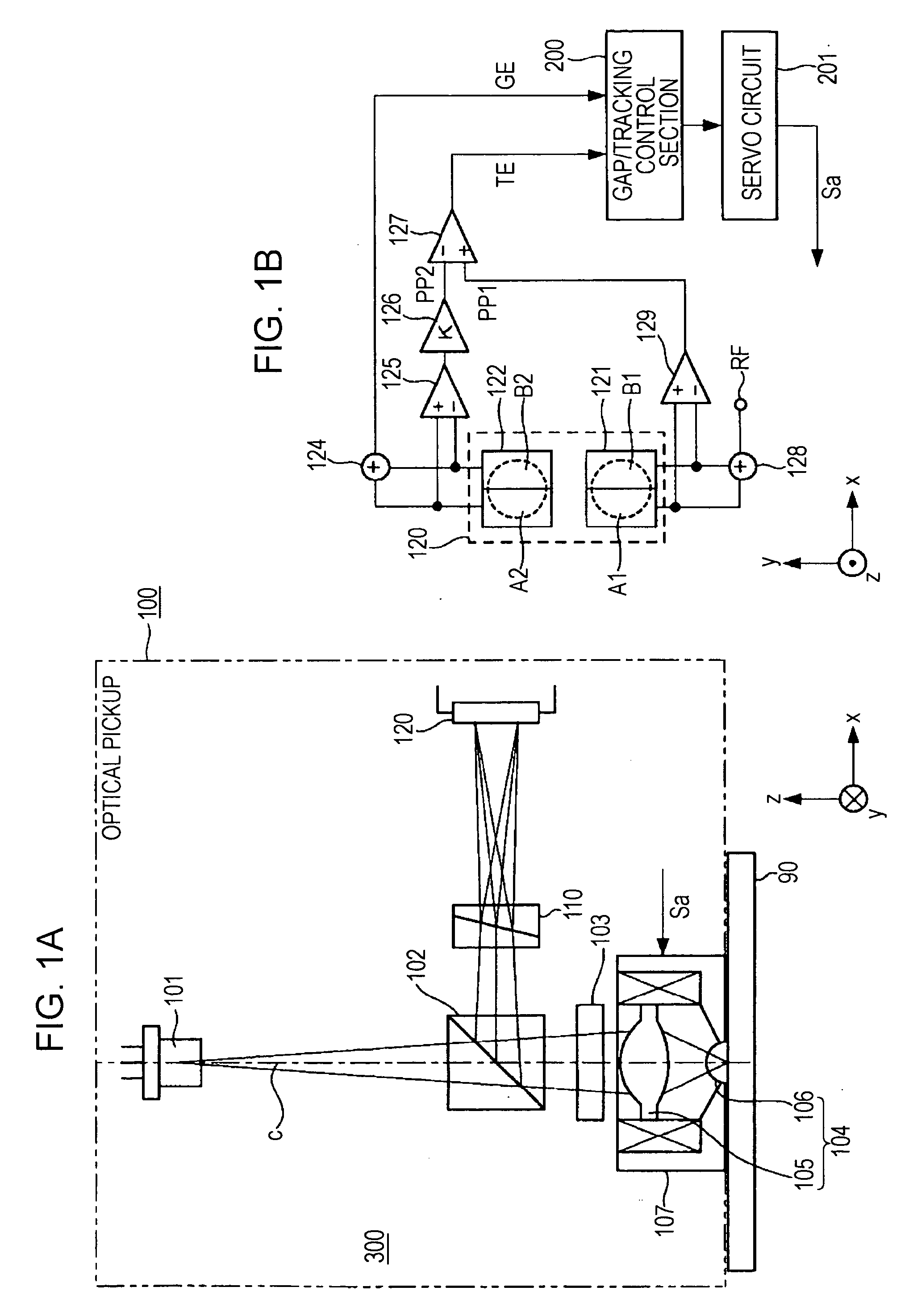
[0083]FIGS. 7A and 7B are schematic diagrams of an optical recording / reproducing apparatus according to the present invention. FIG. 7A is a schematic side-view diagram of an optical pickup according to an embodiment of the present invention, and FIG. 7B is a schematic diagram of the main portion of an optical recording / reproducing apparatus according to an embodiment of the present invention, including the planar structure of the detecting section of the optical pickup shown in FIG. 7A.
[0084] As indicated by the two-dot chain line in FIG. 7A, the optical pickup 100 includes a light source 101 such as a semiconductor laser, an optical system 300 that irradiates an optical recording medium 90 with light from the light source 101 as near-field light by means of a condenser lens 104 with a numerical aperture of 1 or more, and introduces the light reflected by the optical recording medium 90 to a detecting section 140, and a drive section 107 formed by a two-axis or three-axis actuator o...
first embodiment
[0086] In this case as well, an optical lens 105 and a near-field-light radiating section 106 such as an SIL are provided as the condenser lens 104. Since the SIL used is the same as that described with reference to the first embodiment mentioned above, description thereof is omitted.
[0087] In the optical pickup 100 configured as described above, light emitted from the light source 101 is passed through the beam splitter 102 to be incident on the ¼ wavelength plate 103. The λ / 4 plate 103 is placed with its crystal axis tilted by 45° with respect to the incident polarization direction, and causes incident light to emerge as circularly polarized light. This emergent light is made incident on a signal-recording surface of the optical recording medium 90 as near-field light by the condenser lens 104.
[0088] The light reflected by the surface of the optical recording medium 90 is made incident on the λ / 4 plate 103 again via the near-field-light radiating section 106 and the optical lens ...
third embodiment
[0106]FIGS. 9A and 9B are schematic diagrams of an optical recording / reproducing apparatus according to the present invention. FIG. 9A is a schematic side-view diagram of an optical pickup according to an embodiment of the present invention, and FIG. 9B is a schematic diagram of the main portion of an optical recording / reproducing apparatus according to an embodiment of the present invention, including the planar structure of the detecting section of the optical pickup shown in FIG. 9A.
[0107] As indicated by the two-dot chain line in FIG. 9A, the optical pickup 100 includes a light source 101 such as a semiconductor laser, an optical system 300 that irradiates an optical recording medium 90 with light from the light source 101 as near-field light by means of a condenser lens 104 with a numerical aperture of 1 or more, and introduces the light reflected by the optical recording medium 90 to a detecting section 160, and a drive section 107 formed by a two-axis or three-axis actuator o...
PUM
 Abstract
Description
Claims
Application Information