
Self-installable switchable antenna

a switchable antenna and self-installation technology, applied in the direction of antennas, transmission, wireless communication, etc., can solve the problems of insufficient reception signal, change the location of obstacles relative to receivers or transmitters, and move in the environment, so as to optimize the diversity of antenna systems and increase system gain. , the effect of optimizing spatial diversity

Inactive Publication Date: 2007-07-26
WI LAN INC
View PDF9 Cites 52 Cited by
  • Summary
  • Abstract
  • Description
  • Claims
  • Application Information

AI Technical Summary

Benefits of technology

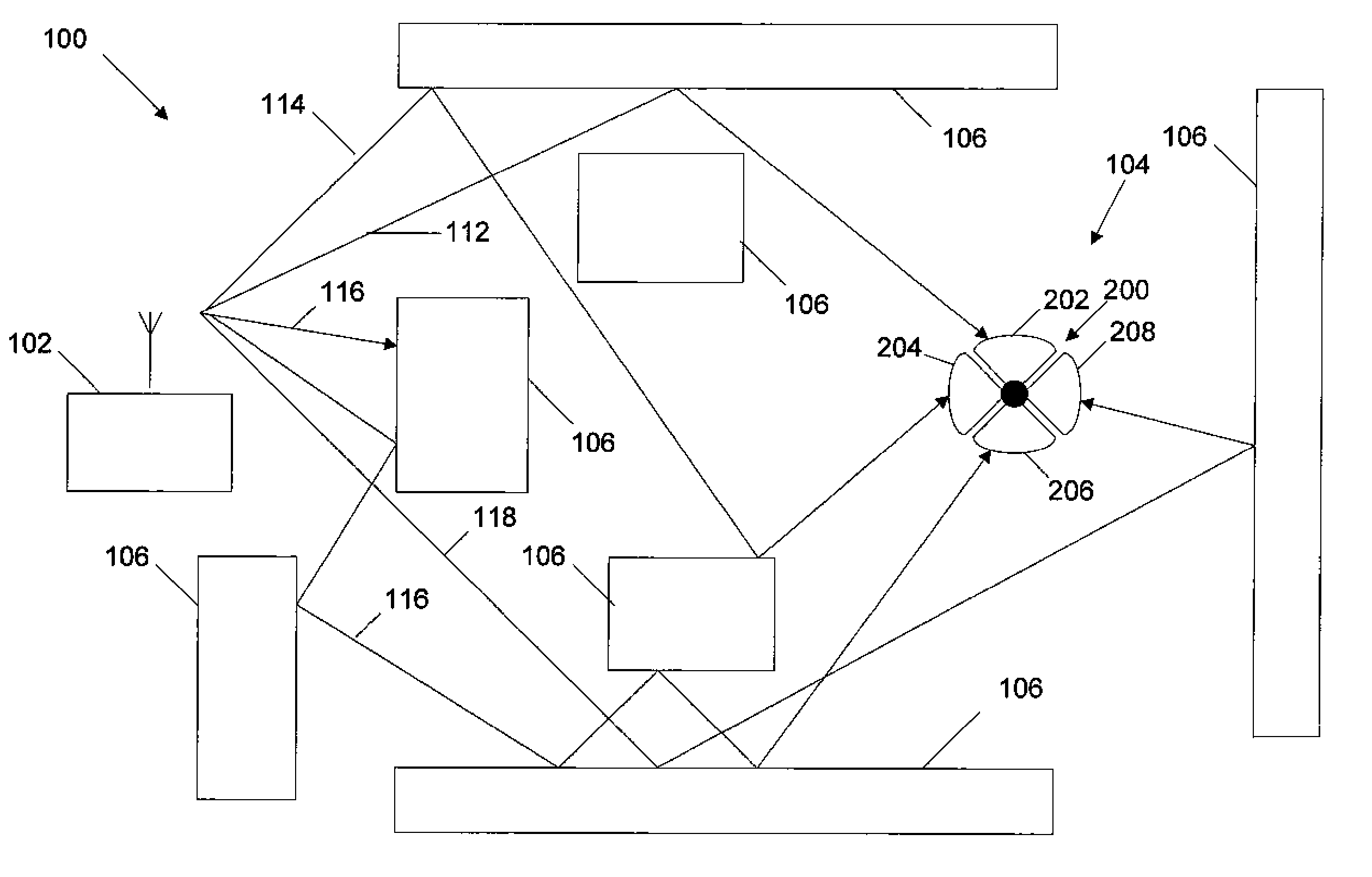
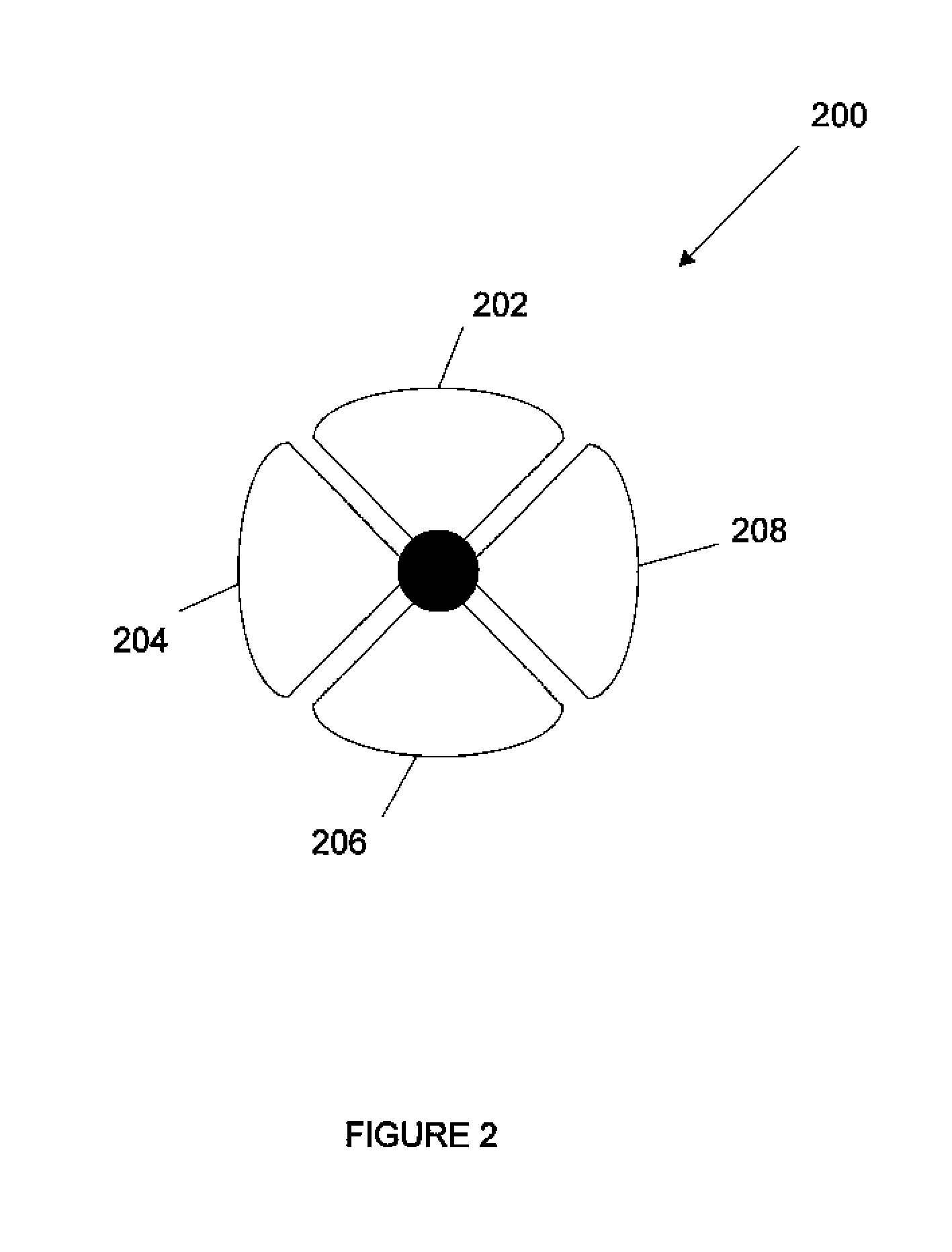
[0013] In accordance with the invention, it is desirable to optimize an antenna system diversity in Non Line-of-Sight (NLOS) or Obstructed Line-of-Sight (OLOS) propagation environments when two or more receive antennas are employed. In other words, it is desirable to optimize spatial diversity for systems that employ one or more antenna feeds that are operating in heavy multipath fading environments. It is also desirable to provide characteristics of omni-directional antenna coverage in NLOS or OLOS environments while also increasing the system gain. The system is self-installable in customer premises equipment (CPE) or Subscriber Station (SS), especially in NLOS environments where a direct antenna alignment is not possible by optical means. The system is also adaptive to support antenna alignment for time-varying NLOS or OLOS propagation environments.

Problems solved by technology

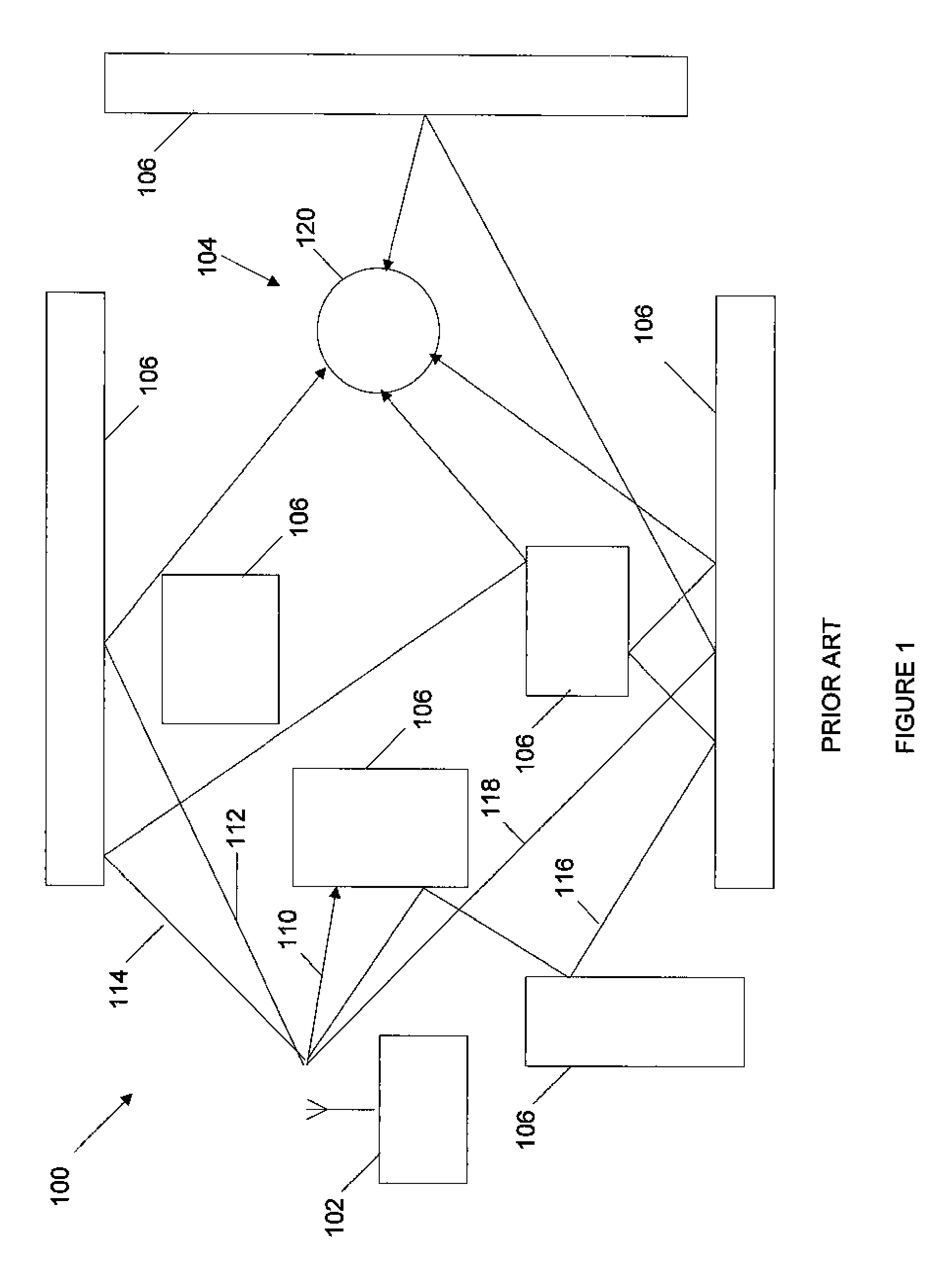
For example, in a wireless LAN, the obstacles within the environment move, such as people walking, or furniture or equipment being moved.
In addition, if the wireless receiver or transmitter are mobile, their movement also changes the location of the obstacle relative to the receiver or transmitter.
In a typical environment where a wireless network 100 operates there are also obstacles 106.
While an omni directional antenna can receive signals from any direction, the received signal is not optimal because there is no antenna gain.
However, because the wireless environment may be changing a fixed directional antenna may not provide adequate performance.

Method used


Image

  • Self-installable switchable antenna
  • Self-installable switchable antenna
  • Self-installable switchable antenna

Examples


Embodiment Construction

” one will understand how the features of the system and methods provide several advantages over traditional framing techniques.

[0013] In accordance with the invention, it is desirable to optimize an antenna system diversity in Non Line-of-Sight (NLOS) or Obstructed Line-of-Sight (OLOS) propagation environments when two or more receive antennas are employed. In other words, it is desirable to optimize spatial diversity for systems that employ one or more antenna feeds that are operating in heavy multipath fading environments. It is also desirable to provide characteristics of omni-directional antenna coverage in NLOS or OLOS environments while also increasing the system gain. The system is self-installable in customer premises equipment (CPE) or Subscriber Station (SS), especially in NLOS environments where a direct antenna alignment is not possible by optical means. The system is also adaptive to support antenna alignment for time-varying NLOS or OLOS propagation environments.

[001...


PUM


Abstract

A system, method, and apparatus for selecting a set of antennas, for use during operation of a radio system, from a plurality of antennas. The system, method and apparatus may include selecting one antenna that is part of an array of antennas. Then measuring characteristics of radio signals received at the antenna. The selection and measuring of characteristic is repeated for a desired number of antennas in the array. Then, the measurements are combined, and the combinations of antennas are ranked based upon the combined measurement. From the ranking combinations of antennas are selected for use during operation of a radio system.

Description

RELATED APPLICATIONS [0001] This application claims priority to U.S. provisional patent application Ser. No. 60 / 749,401, filed Dec. 12, 2005, entitled “Design of a System and Method for Switchable Antenna Selection Based on an Optimzed Configuration,” and U.S. provisional application Ser. Nos. 60 / 763,196, filed Jan. 27, 2006, and 60 / 774,428 filed Feb. 17, 2006, both entitled “Design of a Self-Installable System and Method for Switchable Antenna Selection Based on a Quality Ranking of OFDM and OFDMA Signals” all of which are hereby incorporated by reference in their entirety.BACKGROUND [0002] 1. Field of the Invention [0003] This invention relates to multi-antenna systems for communication systems and more particularly to selection of antenna within a multi-antenna system for use in communication systems. [0004] 2. Description of Related Art [0005] A conventional wireless communication system facilitates two-way communication between a plurality of subscriber units and a wireless net...

Claims


Application Information

Patent Timeline
Patent Type & Authority Applications(United States)
IPC IPC(8): H04B1/00H04M1/00
CPCH01Q1/246H01Q3/24H01Q21/06H04W24/00H04B7/0817H04B7/084H04B7/0874H04B7/0805
Inventor VIOREL, DORIN G.MURIAS, RONALD G.SESHADRI, JAGAN N.
Owner WI LAN INC
Learn More