Method of manufacturing a turbomachine component that includes cooling air discharge orifices

a technology of turbomachine and cooling air, which is applied in the direction of forging/pressing/hammering equipment, foundry patterns, forging/pressing/hammering equipment, etc., can solve the problems of reducing the efficiency of the manufacturing process, and affecting the quality of the product. achieve the effect of convenient optimization

Active Publication Date: 2007-08-02
SN DETUDE & DE CONSTR DE MOTEURS DAVIATION S N E C M A
View PDF9 Cites 7 Cited by
  • Summary
  • Abstract
  • Description
  • Claims
  • Application Information

AI Technical Summary

Benefits of technology

[0012]By producing this orifice portion on the wax pattern of the part, in such a way that it is formed by casting, this shape can be easily optimized for each emission on the profile of the stream. Complicated and expensive use of the electrical discharge machining technique is avoided and such a method is compatible with the manufacture of multiple airfoil distributor sectors by casting.
[0013]Most often, said first portio

Problems solved by technology

These discharges carry away particles of material and progressively erode the surface of the workplace.
The following problems with this technique are encountered
The electrode, whatever its shape, even if it allows rounded wall portions to be produced inside the cavity, cannot prevent sharp edges remaining.
These edges are the site of stress concentrations and run the risk of being crack initiators.
Such a practice does

Method used


Image

  • Method of manufacturing a turbomachine component that includes cooling air discharge orifices
  • Method of manufacturing a turbomachine component that includes cooling air discharge orifices
  • Method of manufacturing a turbomachine component that includes cooling air discharge orifices

Examples


Embodiment Construction

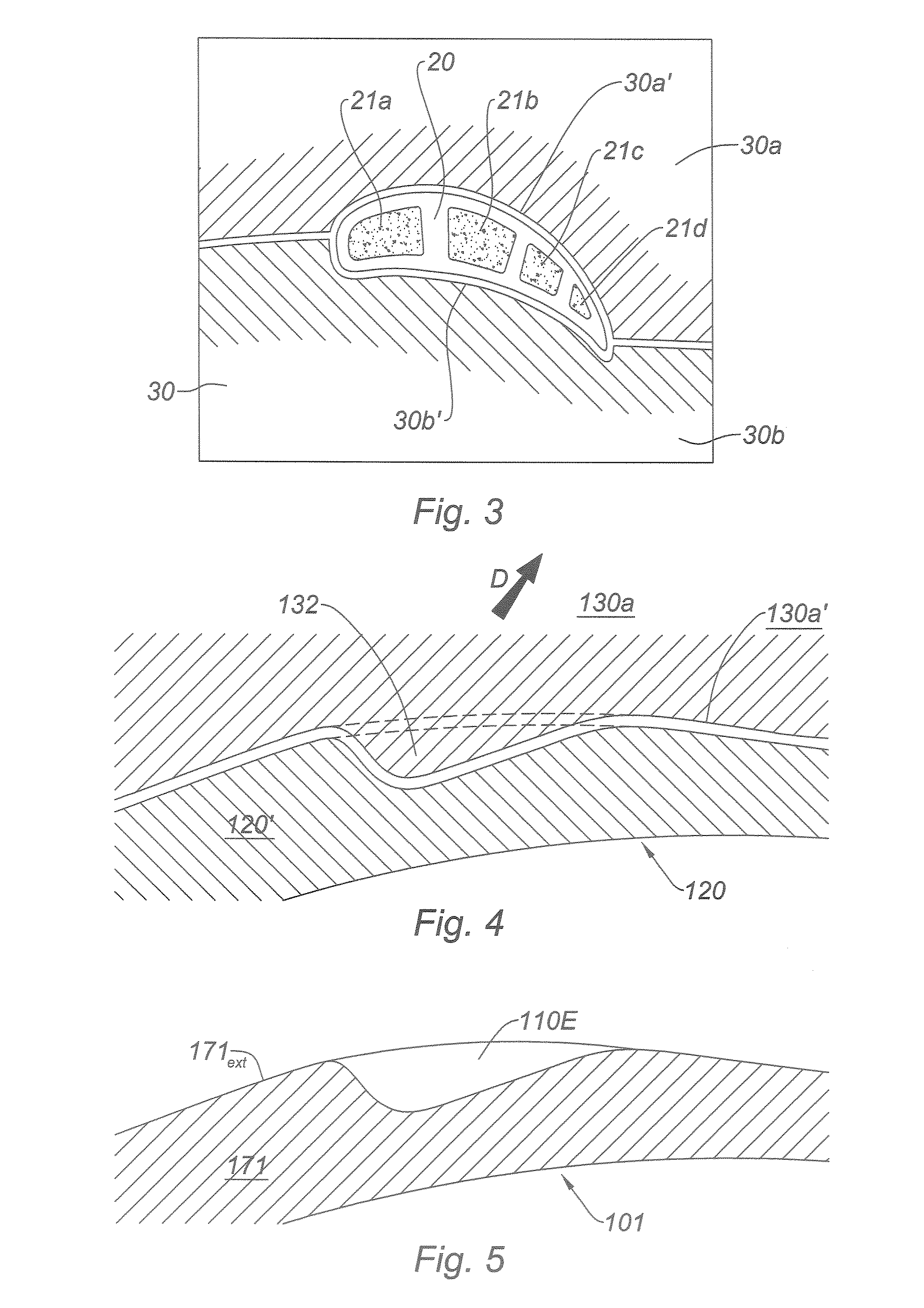
[0030]According to the invention, it is proposed to produce said first, flared, portion of the orifices directly in the wax pattern. Preferably, the wax mold into which the wax is injected has the impression of the first portions of the orifices.

[0031]FIG. 4 shows a sectional view at the internal surface 130a′ of the mold 130a and the pattern through a protuberance 132 for molding a first portion according to the invention. The elements of the invention that correspond to those of the prior art have the same reference but increased by 100. The protuberance 132 has the shape of the first portion that it is desired to impress in the wall 120′ of the wax pattern 120. To meet the demolding constraints, the faces of the protuberance do not include a part making an angle below a limiting demolding angle relative to the direction of demolding in this region, shown by the arrow D. When the mold consists of a plurality of elements with a specific insert for the protuberance or a group of pro...


PUM

PropertyMeasurementUnit
Radiusaaaaaaaaaa
Radiusaaaaaaaaaa
Shapeaaaaaaaaaa

Abstract

The present invention relates to a method of producing cooling fluid discharge orifices in the wall (171) of a part manufactured by the technique of lost wax casting in which a pattern of the part is produced in a wax mold, the orifices having a first portion (110E) emerging at the external surface (171ext) of the wall. The method consists in making cavities in the wax pattern that correspond to the first portions (110E) of said orifices of the part.
Thus it is possible to produce cooling air discharge orifices without sharp edges.

Description

[0001]The present invention relates to the cooling of turbomachine components by an air film.BACKGROUND OF THE INVENTION[0002]To increase the performance of a gas turbine engine, it is necessary to increase the temperature of the gases leaving the combustion chamber. The components of the engine bathed by these gases are therefore subjected to high thermomechanical stresses. They are protected by making cooling air drawn off from the compressor flow into channels provided beneath the wall and discharging said air into the gas stream via small-diameter orifices that are made so as to form a film of protective gas between the wall and the flow of hot gas. The components affected by this treatment are essentially the distributor sectors, consisting of one or more radial airfoils between two platforms in ring sectors by which the gas stream is bounded, and also the moving blades of the first turbine stages. The mechanical behavior and the lifetime of the components are improved by this ...

Claims


Application Information

Patent Timeline
IPC IPC(8): B23P19/04
CPCB22C7/02F01D5/186F05D2250/52B22C9/10F05D2230/21Y10T29/4932F05D2250/324Y10T29/53635Y10T29/49341Y10T29/53617Y10T29/53613F05D2260/202
Inventor ALAUX, THIERRY HENRI, RAYMONDHUCHIN, PATRICK EMILIEN, PAUL, EMILEROSSET, PATRICE JEAN-MARCSOULALIOUX, BORIS
Owner SN DETUDE & DE CONSTR DE MOTEURS DAVIATION S N E C M A
Why Eureka
Try Eureka